Views: 146
Tiandy Ip Camera Installation Instructions, Confirm that there is enough space at the installation site to accommodate the product and its mounting structural part. Confirm that the carrying capacity of the ceiling, wall and bracket on which the network camera is installed must be able to support the total weight of network camera and its mounting structural part, with a 4 times of safety factor.
- Basic requirements
Ensure that all electrical work must be conducted in accordance with the latest electrical regulations, fire regulations and related regulations; check whether the packaging is damaged, equipment and accessories are complete, and determine whether the application places and installation methods of network camera product meet the requirements; please contact the dealer if necessary, please use the product according to the requirements of the working environment.
Tiandy Ip Camera Installation Instructions
Read More :
- Common installation tools:
Prepare the tools actually required according to the actual situations
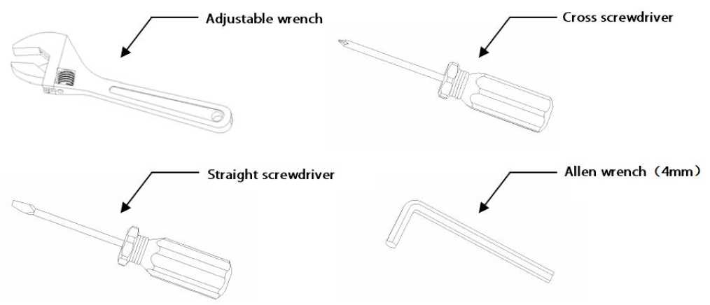
Common installation tools
- Check the strength of the construction of installation space and installation site
Confirm that there is enough space at the installation site to accommodate the product and its mounting structural part. Confirm that the carrying capacity of the ceiling, wall and bracket on which the network camera is installed must be able to support the total weight of network camera and its mounting structural part, with a 4 times of safety factor.
Please keep all packaging materials of network camera
After unpacking the network camera, please keep the original packaging materials of network camera properly, and pack the network camera product properly using the packaging materials of network camera and return it to the supplier for handling in case of any problem.
Note: Non-original packaging materials may cause accidental damage during transportation.
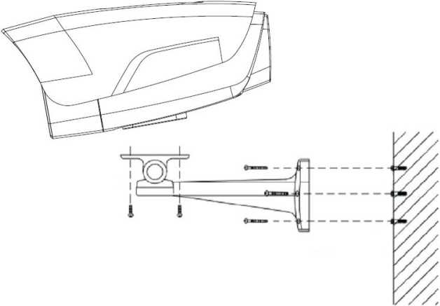
Installation diagram of HD network IR integrated machine
Steps:
- Mark the positions of holes for mounting camera on the wall using an ink pen.
- Make holes on the marked positions using an electric drill.
- Drive the expansion rubber plug into the hole.
- Fasten the wall mounting bracket on the wall with screws.
- Take out the camera in the packaging box, and fasten the camera on the universal joint of bracket with screws.
- Adjust the universal joint of bracket to a proper position and then tighten the screws.
- Finally, remove the protective film on the IR anti-reflection plate (some models are provided with IR anti-reflection plates, please clean the cleaning of the IR anti-reflection plate, to avoid oil stains and scratches).
Note:
- Brackets must be purchased separately.
- The mounting hole of camera is 5.5mm deep. Do not use excessively long screws.
- The mounting surface of camera must have sufficient bearing capacity.
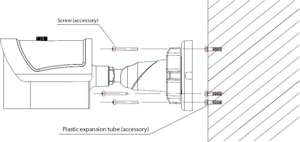
Installation Diagram of HD Network IR Integrated Machine (MINI) -V1.0
Steps:
- Mark the positions of holes for mounting camera on the wall using an ink pen.
- Make holes on the marked positions using an electric drill.
- Drive the expansion rubber plug into the hole that has just been made.
- Take out the camera in the packaging box and fasten the wall mounting bracket on the wall with 3 screws.
- Adjust the universal joint of bracket to the proper position.
Note: The mounting surface of camera must have sufficient bearing capacity.
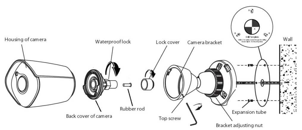
Installation Diagram of HD Network IR Integrated Machine (MINI) -V2.0
Steps:
- Unscrew the top screw and remove the camera bracket. Unscrew the back cover of camera according to the mark, unscrew the waterproof lock on the back cover, and take out the rubber rod.
- Paste the positioning stickers (accessories) on the wall where the camera needs to be installed, drill holes according to hole position B, and then drive the expansion tube (accessory) into the hole. Hole position A is the outlet hole. If necessary, drill holes according to the hole position. Pass the network cable through the camera bracket, and then fasten the bracket on the wall with 3 self-tapping screws (accessories). Pass the network cable through the waterproof lock and the back cover of camera.
- Equip the network cable that has passed through the wire lock with RJ-45 terminal and power terminal.
If the camera is powered by means of POE, the wiring method of RJ-45 is as follows:
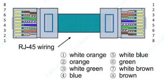
POE power supply-wire sequence diagram
If the camera is powered by means of non-POE, the wiring method of RJ-45 is as follows:
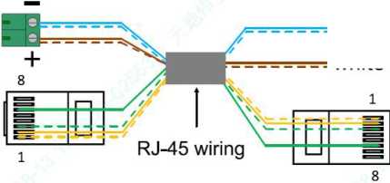
@ white orange
® orange
® white green
white blue / blue
= white brown / brown
® green
Non-POE power supply-wire sequence diagram
- Tighten the back cover to the camera housing, adjust the length of cable, and then tighten the waterproof lock to the marked position. (Note: Please keep the back cover aligned with the scale on the camera housing during the adjustment of waterproof lock).
- Fasten the camera housing to the bracket and tighten the top screw. Loosen the bracket adjusting nut on the camera bracket, adjust the camera angle, and tighten it after adjusting the picture to the required scene. Remove the protective film from the housing and complete the installation.
Note: The mounting surface of camera must have sufficient bearing capacity.
(Unit: mm)
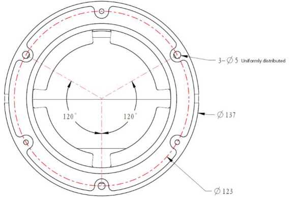
Installation Diagram of HD Network IR Dome Camera-V2.0
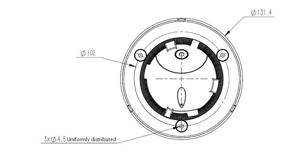
Installation Diagram of HD Network IR Dome Camera-V3.0/V4.0
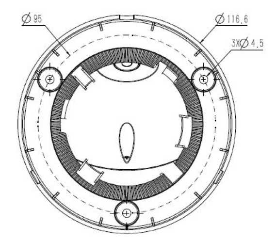
Installation Diagram of HD Network IR Dome Camera-V5.0
Steps:
- Take out the camera in the packaging box, loosen the 3 mounting screws on the housing of V2.0 equipment, and remove the chassis. Rotate the chassis of V3.0/V4.0/V5.0 equipment to the indicated position and remove the chassis.
- Mark the mounting hole position of camera on the wall with a ink pen, make holes on the indicated hole position with a electric drill, and drive the expansion rubber plug into the hole that has just been made.
- Fasten the chassis on the wall with screws. Reassemble the components removed in Step 1. Adjust the direction of camera to a suitable position, and tighten the 3 mounting screws on the housing of V2.0 equipment. Rotate the component of V3.0/V4.0/V5.0 equipment into the snap position and then fasten it.
Note: The mounting surface of camera must have sufficient bearing capacity.
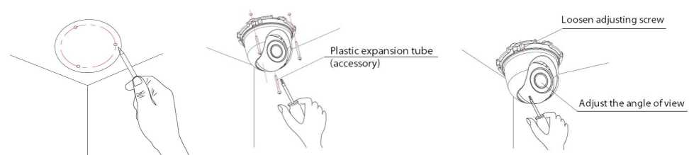
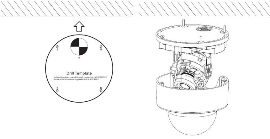
Installation Diagram of HD Network IR Dome Camera (MINI)
Steps:
- Mark the positions of holes for mounting camera on the wall using an ink pen.
- Make holes at the indicated position with an electric drill, and drive the expansion rubber plug into the hole.
- Take out the camera in the packaging box, remove the dome cover, and fasten the dome to the ceiling with screws.
- Loosen the adjusting screw, adjust the camera lens to an appropriate angle, and then re-fasten the adjusting screw.
- Align the dome cover with the mounting position of the base, and then rotate and fasten it.
Note: The mounting surface of camera must have sufficient bearing capacity.
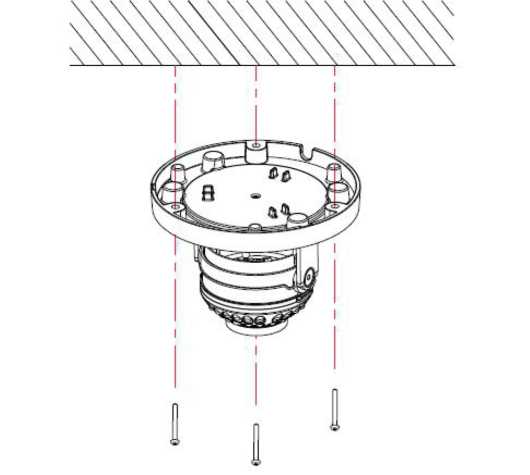
Installation Diagram of (Non-) Safe IR Dome Camera -V1.0
Steps:
- Mark the positions of holes for mounting camera on the wall using an ink pen. Make holes on the marked positions using an electric drill, drive the expansion rubber plug into the hole.
- Take out the camera in the packaging box, and remove the dome cover; and then fasten the dome to the ceiling using mounting screws.
- Loosen the adjusting screw, adjust the camera lens to an appropriate angle, and then re-fasten the adjusting screw.
- Align the dome cover with the mounting position of the base, and then fasten it by turning.
- Finally, remove the protective film on the dome cover (please protect the transparent cover of dome, to avoid oil stains and scratches).
Note:
- The mounting surface of camera must have sufficient bearing capacity.
- Please use the dome camera as soon as possible after unpacking.
- Fog may be caused when disassembling the equipment in wet environments.
- To ensure the waterproof effect, please tighten the screws.
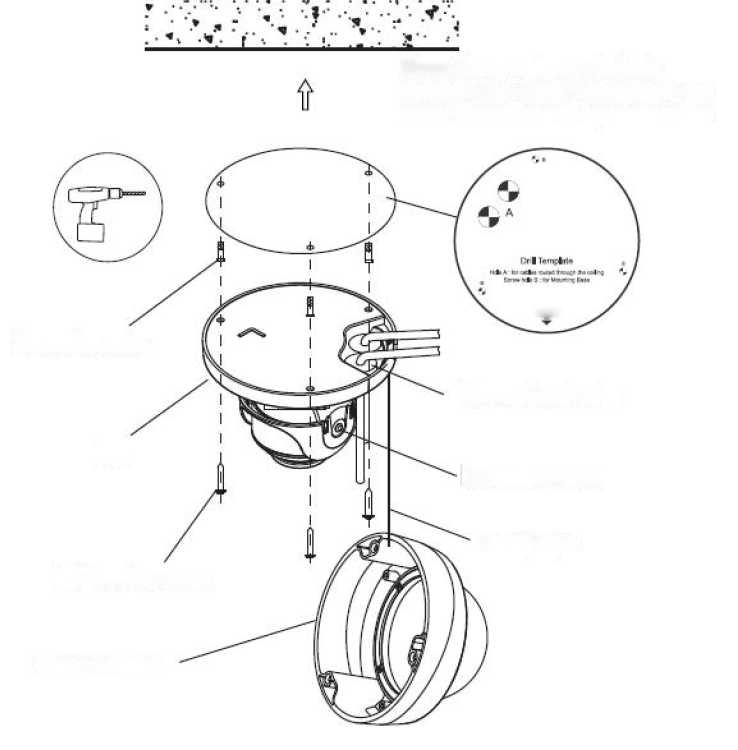
Frgr4
Self-tapping screw
Dome housing
Through-hole plug
Mounting screw
Safety rope
Note: Please estimate the hole diameter and depth according to the actual dimensions of expansion tube
Base
Expansion tube
Installation Diagram of HD Network Safe (Non-) IR Dome Camera-V2.0
Steps:
- Mark the mounting hole position of camera on the wall with a ink pen or positioning sticker, make holes on the indicated hole position with a electric drill, and drive the expansion rubber plug into the hole.
- For models without a tail cable: loosen the screws, remove the dome housing, pass the power cord, audio cable (optional) and network cable through the cable hole plug at the base of dome, with a cable diameter of 3-5mm (Note: pull back after passing the cable to ensure water resistance), and then fasten the base of dome to the wall or ceiling. Connect the power cable and audio cable (optional) to the corresponding interface of camera. After making the plug of the network cable, insert it into the Ethernet interface of camera, and then fasten the base of dome base to the wall or ceiling.
- For models with a tail cable: connect the power supply, network cable and other parts to the 29
corresponding interface of camera. Loosen the screws, remove the dome housing, and fasten the base of dome to the wall or ceiling.
- Adjust the lens to the required scene, and then tighten the two mounting screws. The recommended torque is 6-7kgf.cm.
- Before installing the equipment in a humid environment, please replace the desiccant and then fasten the dome housing to the base of dome, and finally remove the protective film on the housing (Note: do not crimp when installing dome housing on the base).
Note:
- The mounting surface of camera must have sufficient bearing capacity.
- Fog may be caused when disassembling the equipment in wet environments.
- To ensure the waterproof effect, please tighten the screws.
Wall
Mounting hole position
Universal joint of bracket \
Lens
Screw that meet BS standards
Expansion rubber plug
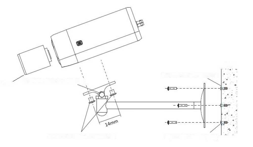
Installation Diagram of HD Network Gun Camera
Steps:
- Mark the positions of holes for mounting camera on the wall using an ink pen.
- Make holes on the marked positions using an electric drill.
- Drive the expansion rubber plug into the hole.
- Fasten the wall mounting bracket on the wall with screws.
- Take out the camera in the packaging box, align the two screws with the camera screw mounting position, and then tighten them by turning.
- Adjust the universal joint of bracket to a proper position and then tighten it.
Note:
- Brackets must be purchased separately.
- The mounting surface of camera must have sufficient bearing capacity.
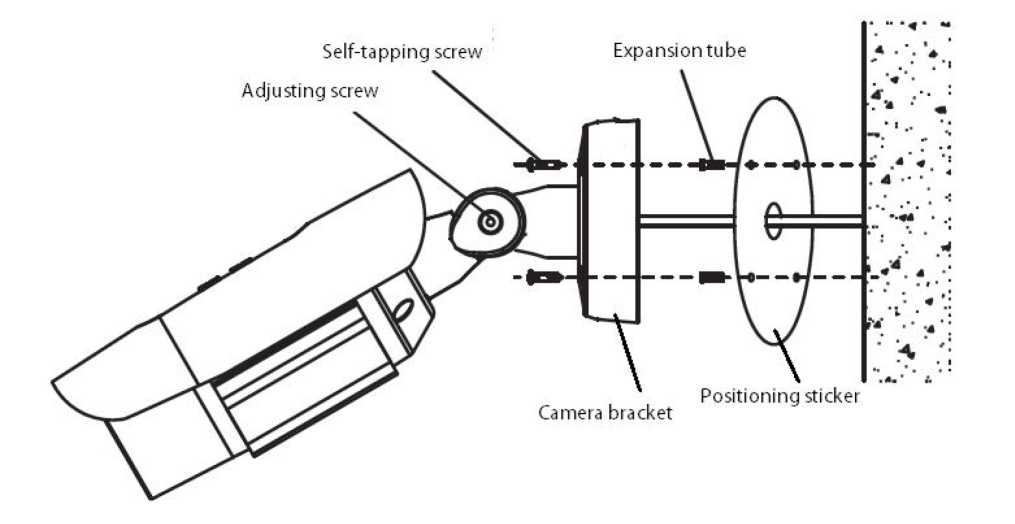
Installation Diagram of HD Network Zoom IR Gun Camera (with integrated bracket) Steps:
- Paste the positioning stickers on the wall.
- Make holes on the marked positions using an electric drill.
- Drive the expansion rubber plug into the hole.
- Fasten the wall mounting bracket on the wall with screws.
- Adjust the screw, rotate the angle to the target position, and then tighten the screw.
- Adjust the sunshade back and forth, to avoid blocking video or IR light.
Note: The mounting surface of camera must have sufficient bearing capacity.
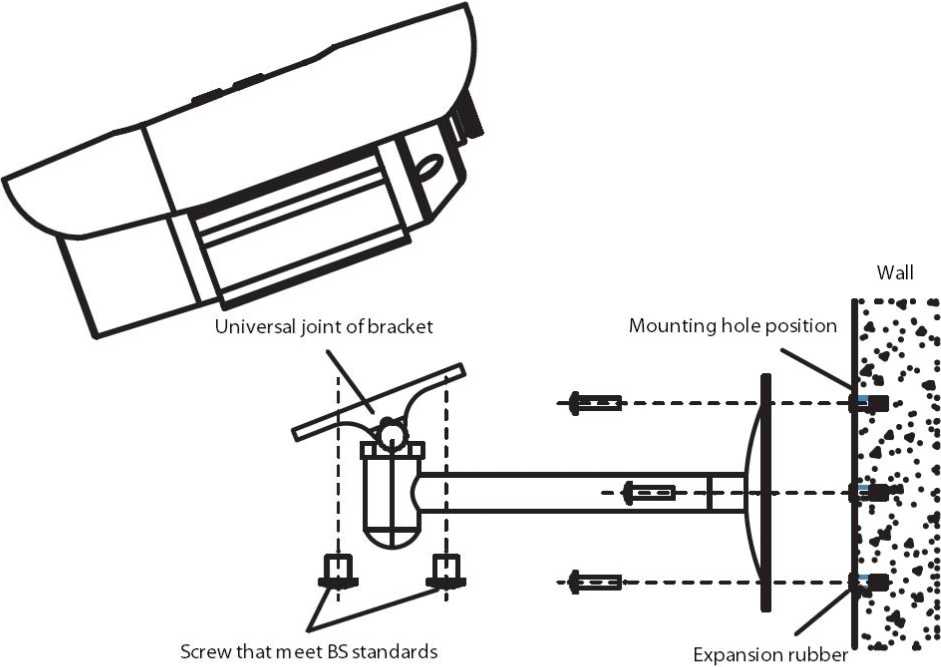
Installation Diagram of HD Network Zoom IR Gun Camera (without integrated bracket)
Steps:
- Mark the positions of holes for mounting camera on the wall using an ink pen.
- Make holes on the marked positions using an electric drill.
- Drive the expansion rubber plug into the hole.
- Fasten the wall mounting bracket on the wall with screws.
- Align the two screws with the screw mounting position of camera, and then tighten them by turning.
- Adjust the universal joint of bracket to a proper position and then tighten it.
Note:
- Brackets must be purchased separately.
- The mounting surface of camera must have sufficient bearing capacity.
Installation Diagram of HD Network Zoom IR Dome Camera-V2.0
Steps:
- Paste the positioning stickers on the wall.
- Make holes on the marked positions using an electric drill.
- Drive the expansion rubber plug into the hole.
- Fasten the base of camera to the wall with screws.
- Rotate the lens to the target angle.
- Before installing the equipment in a humid environment, please replace the desiccant and then fasten the dome housing to the base of dome, and finally remove the protective film on the housing (Note: do not crimp when installing dome housing on the base).
Note:
- The mounting surface of camera must have sufficient bearing capacity.
- Fog may be caused when disassembling the equipment in wet environments.
- To ensure the waterproof effect, please tighten the screws.
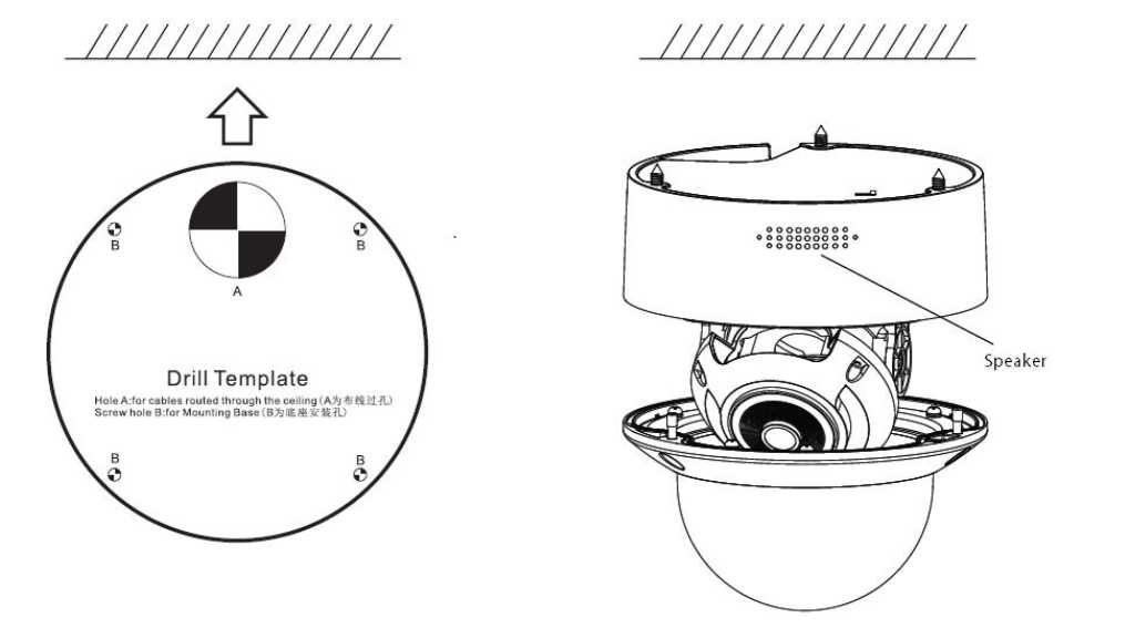
Installation Diagram of HD Network Zoom IR Dome Camera-V3.0peaker
Steps:
- Paste the positioning stickers on the wall.
- Make holes on the marked positions using an electric drill.
- Drive the expansion rubber plug into the hole.
- Fasten the base of camera to the wall with screws.
- Rotate the lens to the target angle.
- Before installing the equipment in a humid environment, please replace the desiccant and then fasten the dome housing to the base of dome, and finally remove the protective film on the housing (Note: do not crimp when installing dome housing on the base).
Note:
- The mounting surface of camera must have sufficient bearing capacity.
- Fog may be caused when disassembling the equipment in wet environments.
- To ensure the waterproof effect, please tighten the screws.
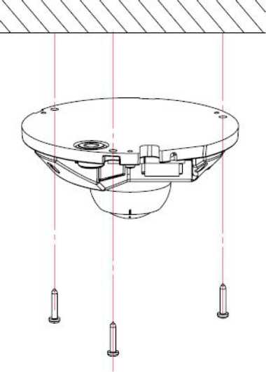
Installation Diagram of HD Network Special-shaped Safe IR Dome Camera
Steps:
- Make a hole at the mounting position according to the dimensional drawing, and drive the expansion rubber plug into the hole.
- Take out the camera in the packaging box, and remove the dome cover; and then fasten the dome to the ceiling using mounting screws.
- Loosen the adjusting screw, adjust the camera lens to an appropriate angle, and then re-fasten the adjusting screw.
- Align the dome cover with the mounting position of the base, press down the dome cover and fasten it with screws.
- Finally, remove the protective film on the dome cover (please protect the transparent cover of dome, to avoid oil stains and scratches).
Note: The mounting surface of camera must have sufficient bearing capacity.
-
- Waterproof Construction Specifications
The zoom (non-) IF dome camera is divided into two models: model with tail cable and model with incoming cable. The model with incoming cable is equipped with a waterproof lock, a single hole supports the wire diameter of 3-5mm. For the lock with 4 holes, please keep the original plugs for the holes not used; for the lock with 3 holes, do not puncture the rubbers at the holes not used.
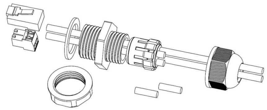
Installation Instructions for Waterproof Lock with 4 Holes
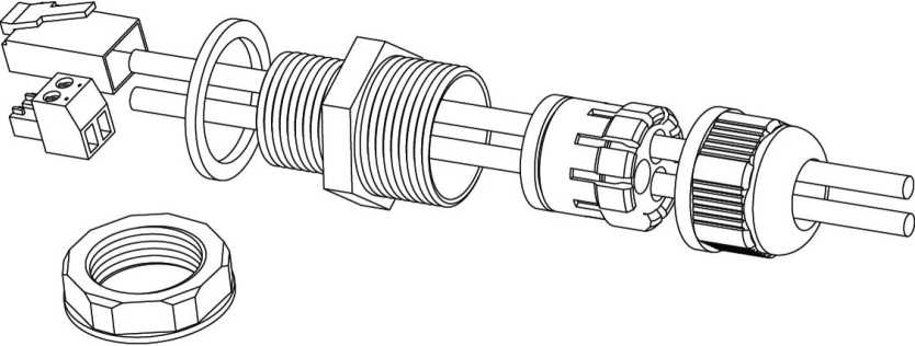
Installation Instructions for Waterproof Lock with 3 Holes
You may select to use side or bottom outlet according to needs, please tighten the waterproof lock with a wrench, to prevent water and fog from entering. Do not open the protective guard in humid environments, to prevent fogging. To prevent frogging, some models are equipped with new desiccants, please replace desiccants for some models before installing the protective guard.
For products with tail cables and waterproof design, please take the following waterproof measures during installation:
- The power port must be wrapped with waterproof tape to ensure water resistance, otherwise, there may be a risk of short circuit.
- For the waterproofing of Ethernet interface, please refer to the following figure for construction and installation.
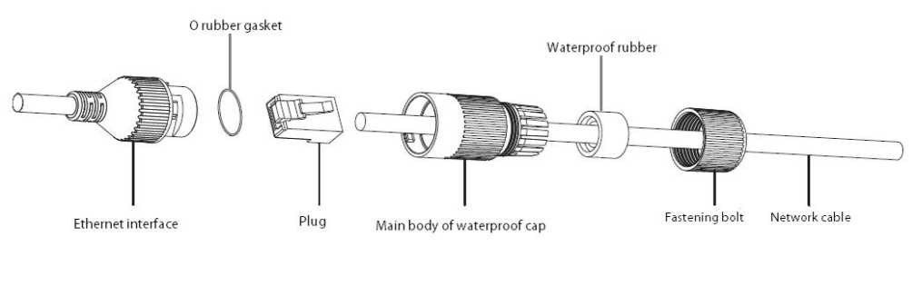
Waterproof installation instructions of network cable
- Please lower the SR of the tail cable to the position below the camera, as shown in the figure below.
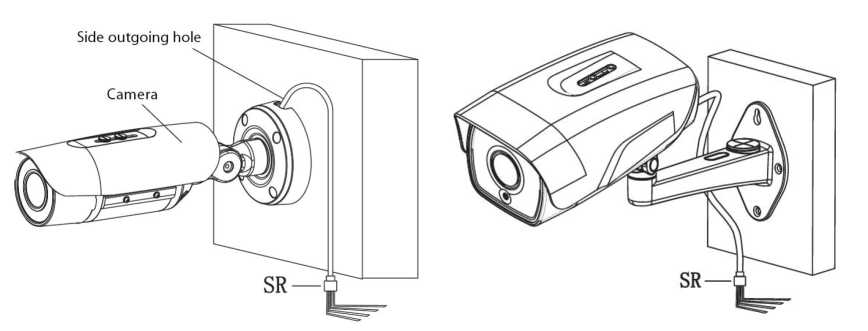
Installation Diagram of Tail Cable
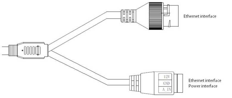
I-type camera tail cable interface
Interface Description:
| Type | Functions | Name | Description |
| System
interface |
Power
supply |
DC12V
GND |
Input of DC12V ± 10%, please select matching power supply according to suggestions
Some models are powered by POE and can provide DC12V output |
| Ethernet
interface |
ETHERNET | 10M / 100M, RJ45 interface
Supported by some models POE power supply |
|
| Function
interface |
Audio input | A_IN
GND |
Linear signal input, input voltage <1V
GND is the common terminal |
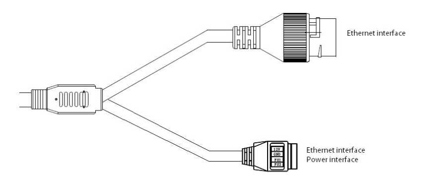
Type II camera tail cable interface
Interface Description:
| Type | Functions | Name | Description |
| System
interface |
Power
supply |
DC12V
GND |
Input of DC12V ± 10%, please select matching power supply according to suggestions
Some models are powered by POE and can provide DC12V output |
| Ethernet
interface |
ETHERNET | 10M / 100M, RJ45 interface
Supported by some models POE power supply |
|
| Function
interface |
Function
interface 1 |
FU1
GND |
See label description for details
GND is the common terminal |
| Function
interface 2 |
FU2
GND |
See label description for details
GND is the common terminal |
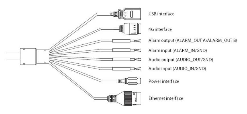
Type III camera tail cable interface
Description:
- The specific vehicle-mounted camera power supply adopts BMW connector and needs to be used with an extension cable. The input voltage supports DC12V – DC24V.
- The line sequence of the extension line is as follows:
Red wire: battery+
Power socket I I |iJm — Black wire: battery
White wire: Ignition wire (ACC)
Extension cord of tail cable (vehicle-mounted model)
Interface Description:
| Type | Functions | Name | Description |
| System
interface |
Power
supply |
DC12V IN | Input of DC12V ± 10%, please select matching power supply according to suggestions
(Excluding special vehicle-mounted camera) Some models are powered by POE and can provide DC12V output |
| Ethernet
interface |
ETHERNE
T |
10M / 100M, RJ45 interface | |
| Extension ports (Optional) | Audio
interface |
AUDIO_IN | Linear signal input, GND is the common terminal, input
voltage: <1V; (optional function) |
| AUDIO_O
UT |
Linear output, GND is the common terminal, used with active speakers; (optional function) | ||
| Alarm
interface |
ALARM_I
N |
Switching signal input, GND is the common terminal
(optional function) |
|
| ALARM_O
UT |
Switching signal output (optional function) | ||
| RS485
interface |
RS485 | A is 485 positive (+), B is 485 negative (-) (optional
function) |
|
| 4G | 4G | 1: GND 2: RS485- (RS485B) 3: RS485 + (RS485A)
4: DC5V (optional function) |
|
| Storage
interface |
Support | USB | 8G – 64G is recommended, please power off the device
before disassembly |
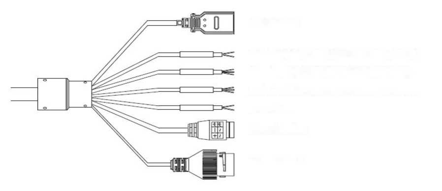
USB interfa ce
Alarm output (ALARM_OUT A/ALARM_OUT B)
Alarm input (ALARMJN1/ALARM JN2/GND)
Audio interface (AUDIO_IN/AUDIO_OUT/GND)
RS485 (A/B)
Power interface
Ethernet interface
Type IV camera tail cable interface
Interface Description:
| Type | Functions | Name | Description |
| System
interface |
Power
supply |
POWER | DC12V ± 10%, Supported by some models AC24V
Please refer to the actual label |
| Earth | Connected to the earth to prevent static electricity / surges from damaging the equipment | ||
| Ethernet
interface |
ETHERNET | 10M / 100M, RJ45 interface | |
| Extension ports (Optional) | Audio
interface |
AUDIO_IN | Linear signal input, GND is the common terminal,
input voltage: <1V (optional function) |
| AUDIO_OUT | Linear output, GND is the common terminal, used with active speaker (optional function) | ||
| Alarm
interface |
ALARM_IN | Switching signal input, GND is the common terminal | |
| ALARM_OUT | Switching signal output | ||
| Control
interface |
RS485 | A is RS485 +, B is RS485- | |
| Storage
interface |
USB | USB | Expandable memory or Wifi module, the recommended memory is 8G – 64G, please power off the device before disassembly |
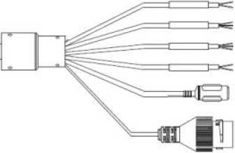 Alarm output (ALARM_OIJT A/ALARM_OUT B)
Alarm input (ALARMJN1/ALARMJN2/GND)
Audio interface (AUDIOJN/AUDIO_OUT/GND)
RS485 (A/B)
Power interface
Ethernet interface
Tail line interface of type V camera
 Interface Description:
| Type | Functions | Name | Description |
| System
interface |
Power
supply |
POWER | DC12V±20%
Please refer to the actual label |
| Ethernet
interface |
ETHERNET | 10M / 100M, RJ45 interface | |
| Extension ports (Optional) | Audio
interface |
AUDIO_IN | Linear signal input, GND is the common terminal,
input voltage: <1V (optional function) |
| AUDIO_OUT | Linear output, GND is the common terminal, used with active speaker (optional function) | ||
| Alarm
interface |
ALARM_IN | Switch signal input, 2 channels supported, GND is the
common terminal |
|
| ALARM_OUT | Switching value or relay output signal output (subject to the actual object) | ||
| Control
interface |
RS485 | A is RS485 +, B is RS485- |
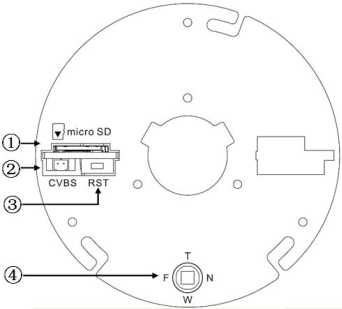
(D micro SD card slot
(2 Analog video output, used with BNC conversion cable (accessory) (supported by some
models)
(3 Reset button
(4 Focusing control for electric lens, press for one-button focusing (supported by some
models)
Internal interface of HD network zoom IR gun
Interface Description:
| Type | Functions | Name | Description |
| System
interface |
Power
supply |
POWER | DC12V (± 10%), Supported by some models AC24V (± 25%) |
| Ethernet
interface |
ETHERNET | 10M / 100M / 1000M (1000M for some models), RJ45
interface, Supported by some models POE |
|
| Reset | RESET | After holding for 5 seconds, the system will restore factory settings | |
| Audio and video interface | Video
output |
VIDEO OUT
/CVBS |
75Qp-p analog video signal; |
| Audio
input |
AUDIO IN | Audio linear input | |
| Audio
output |
AUDIO OUT | Audio linear output | |
| Alarm
interface |
Alarm
Input |
ALARM IN | GND is the common terminal; 1/2 is the 2-way alarm input interface |
| Control
output |
ALARM OUT | 1A / 1B, signal relay output interface | |
| Storage
interface |
TF card | micro SD | 8G – 64G is recommended, please power off the device before disassembly |
| USB | USB | Expandable U disk or Wifi adapter, please power off the |
| Type | Functions | Name | Description |
| device.
Description:
|
|||
| Extension
ports |
485
interface |
RS485A/B | 485 communication interface |
| Motorized lens | T/W/F/N | Motorized lens control, T zoom in / W zoom out / F far / N near
Press for one-button focusing (supported by some models) |
-
- Dimensions of HD Network Zoom (Non-)IR Dome Camera
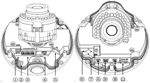
Internal interface of HD network zoom (non-) IF dome camera-V2.0
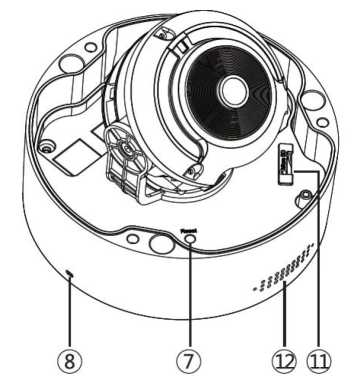
Internal interface of HD network zoom (non-) IF dome camera-V3.0
(1 Power interface, support DC12V (Supported by some models AC24V)
(2 Earthing rod
(3 Signal cable interface, see chassis label for details
(4 USB interface, GND/D+/D-/5V from left to right (supported by some models)
@ Ethernet interface, 10M / 100M / 1000M (some models are 1000M, Supported by some models POE)
(6 Focusing control for electric lens, press for one-button focusing (supported by some models)
(7 Reset button
® Built-in MIC interface
(9 Debugging interface, only used by the manufacturer for debugging
(10 Analog video output, used with BNC conversion cable (accessory) (supported by some models)
(11 micro SD card slot
12 Built-in speaker
Interface Description:
| Type | Functions | Name | Description |
| System
interface |
Power
supply |
POWER | DC12V (± 10%), Supported by some models AC24V (± 25%) |
| Ethernet
interface |
ETHERNET | 10M / 100M / 1000M (1000M for some models), RJ45
interface, Supported by some models POE |
|
| Reset | RESET | After holding for 5 seconds, the system will restore factory settings | |
| Debuggin
g interface |
DEBUG | Debugging interface, only used by the manufacturer for debugging | |
| Audio and video interface | Video
output |
VIDEO OUT
/CVBS |
75Qp-p analog video signal; |
| Audio
input |
AUDIO IN | Audio input (Mic in/Line in) | |
| Audio
output |
AUDIO OUT | Audio linear output | |
| Alarm
interface |
Alarm
Input |
ALARM IN | GND is the common terminal; 1/2 is the 2-way alarm input
interface |
| Control
output |
ALARM OUT | 1A / 1B, signal relay output interface | |
| Storage
interface |
TF card | micro SD | 8G – 64G is recommended, please power off the device before disassembly |
| USB | USB | Expandable U disk or Wifi adapter, please power off the device.
Description: 1. The recommended U disk capacity is 8G – 64G |
| Type | Functions | Name | Description |
| 2. If a micro SD card has been installed, U disk cannot be expanded | |||
| Extension
ports |
485
interface |
RS485A/B | 485 communication interface |
| Motorized lens | T/W/F/N | Motorized lens control, T zoom in / W zoom out / F far / N near
Press for one-button focusing (supported by some models) |
4.4.1. Network Gun Camera-V2.0
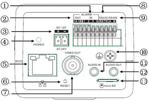
Interface of Type I network gun camera-V2.0
(1 1 and 2 are 2-way alarm inputs, 3 is synchronous switch interface of alarm
(2 Alarm Output
(3 Power interface, support DC12V (Supported by some models AC24V)
(4 Power indicator
(5) Network
(6 Reset button
(7 Analog video output
(8 Extended RS232
(9 Extended RS485
@ Lightning protection earthing wire interface
(11 Audio input
- Audio output
- micro SD card slot
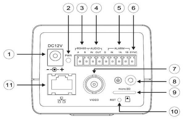
Interface of Type II network gun camera-V2.0
(1) Power interface, support DC12V
(2 Power indicator
(3 Extended RS485 interface
(4 Audio interface
(5) Alarm interface, IN is alarm input, and 1A and 1B are alarm output.
(6 Synchronous switching interface of alarm
(7 Analog video interface
(8 Earthing rod
(9 micro SD card slot
10 Reset button
H Network interface
| Type | Functions | Name | Description |
| System
interface |
Power
supply |
POWER | DC12V (± 10%), Supported by some models AC24V (± 25%) |
| Ethernet
interface |
ETHERNET | 10M / 100M / 1000M (1000M for some models), RJ45
interface, Supported by some models POE |
|
| Reset | RESET | After holding for 5 seconds, the system will restore factory settings | |
| Aperture interface | LENS | Lenses with controlled DC aperture (Supported by some models P-iris aperture lenses) | |
| Audio and video interface | Video
output |
VIDEO OUT
/CVBS |
75Qp-p analog video signal |
| Audio
input |
AUDIO IN | Audio input (Mic in/Line in) | |
| Audio
output |
AUDIO OUT | Audio linear output | |
| Alarm
interface |
Alarm
Input |
ALARM IN | Type I gun camera: G is the common terminal; 1/2 is the two-way input interface of alarm, and 3 is the synchronous switching interface of alarm. The black and white/color mode of camera can be switched by shorting or disconnecting with G.
Type II gun camera: G is the common terminal; IN is the alarm input interface, SYNC is the synchronous switching interface of alarm, and the black and white/color mode of camera can be switched by shorting or disconnecting with G. |
| Control
output |
ALARM OUT | 1A / 1B, signal relay output interface | |
| Storage
interface |
Support | micro SD | The recommended storage capacity is 8G – 64G, please power off the equipment before disassembly |
| Extension
ports |
485
interface |
RS485A/B | 485 communication interface |
| Type | Functions | Name | Description |
| 232
interface |
RX/TX/G | RX is the receiving port / TX is the sending port / G is the reference ground (only supported by Type I) |
4.4.2. Network Gun Camera-V3.0
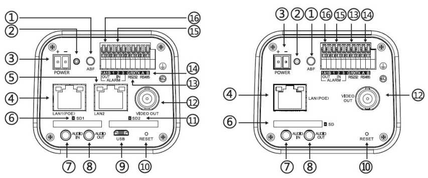
Interface of Type I Network Gun Camera-V3.0 Interface of Type II Network Gun
Camera-V3.0
(1 ABF button: click it to start immediately (supported by some models)
@ Indicator light: if the light is always on in red, the power supply is normal; if the light is flashing in blue, ABF is running
(3 Power interface, support DC12V (Supported by some models AC24V)
(4 Network interface, support POE
(5 Network interface 2 (supported by some models)
(6 SD card slot
(7 Audio input
(8 Audio output
@ micro USB (supported by some models)
® Reset button
@ SD card slot 2 (supported by some models)
@ Analog video output
@ RS 232 interface (supported by some models)
(14 RS 485 interface (supported by some models)
(15 Alarm input, 1 and 2 are alarm inputs, and 3 is the synchronous switching interface of alarm
(16 Alarm output (supported by some models)
| Type | Functions | Name | Description |
| System
interface |
Power
supply |
POWER | DC12V (± 10%), Supported by some models AC24V (± 25%) |
| Ethernet
interface |
ETHERNET | 10M / 100M / 1000M (Supported by some models 1000M),
RJ45 interface, Supported by some models POE |
|
| Reset | RESET | After holding for 5 seconds, the system will restore factory settings | |
| Aperture interface | LENS | Lenses with controlled DC aperture (Supported by some models P-iris aperture lenses) | |
| Audio and video interface | Video
output |
VIDEO OUT
/CVBS |
75Qp-p analog video signal |
| Audio
input |
AUDIO IN | Audio input (Mic in/Line in) | |
| Audio
output |
AUDIO OUT | Audio linear output | |
| Alarm
interface |
Alarm
Input |
ALARM IN | G is the common terminal; 1/2 is the 2-way alarm input interface, and 3 is the synchronous switching interface of alarm. The black and white/color mode of camera can be switched by shorting or disconnecting with G |
| Control
output |
ALARM OUT | 1A / 1B, signal relay output interface | |
| Storage
interface |
SD card | SD | The recommended storage capacity is 8G-256G, please power off the equipment before disassembly |
| Extension
ports |
485
interface |
RS485A/B | 485 communication interface |
| 232
interface |
RX/TX/G | RX is the receiving port / TX is the sending port / G is the reference ground |
It is recommended to run under the operating system environment of Win7 and above. In order to better operate and use the system, and fully reflect the performance and effects, please ensure that the following items are set or installed correctly after the system is successfully installed:
- The display resolution is set to 1920 x 1080 or higher, and the color is set to enhanced color (32-bit), please refer to Windows help document or online help for how to set the resolution and color of monitor.
- Make sure that the font required for this system-Song font is installed in the Windows operating system. If the interface of this system is displayed abnormally, the fonts required by this system may not be installed, or the required fonts have been damaged, and fonts need to be reinstalled.
You need to download ActiveX controls before using this series of network video products for the first time. Before downloading, you need to set the IE browser appropriately to ensure that the controls are downloaded successfully.
Note: Use the IE browser of Windows operating system, to ensure that the version is 8.0 or above. Except for Firefox and Google browsers, please do not use other third-party browsers and any IE browser shell programs such as Maxthon, Window of the World. We do not guarantee that you can log in normally with such software.
If the computer is connected to the camera for the first time, please go to “Internet Options”-“Security”-“Trusted Sites”-“Sites” and add the IP of the camera to the list of “Trusted Sites”. Then set the “Custom Level” and set all the options in “ActiveX Controls and Plug-ins” to “Enable”, to ensure that the computer can download and run the controls normally.
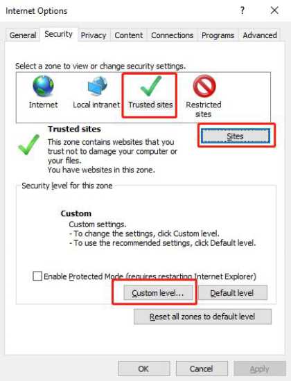
IE Browser-Internet Options
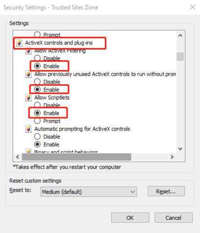
Trusted Site-Custom Level
The default IP address of the device is: 192.168.1.2, subnet mask: 255.255.255.0, gateway: 192.168.1.1. Please set the IP address of the computer and the IP address of the device in the same network segment: for example, set the IP address of the computer to 192.168.1.3 to access the device through IE browser. Open the IE browser, input the IP address of the network video device in the address bar, and click “go” to log in to the device. If it is the first time to use, the following login interface will appear.
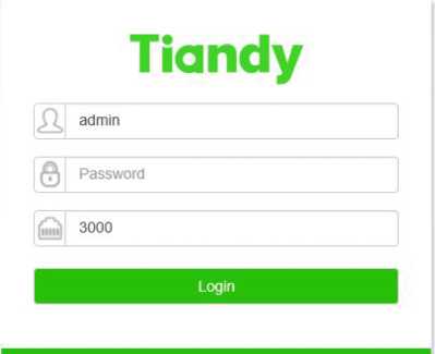
IE login interface
Enter the correct user name and password in the login window, and click “Login” to enter the preview interface later.
Description:
- The default user name is admin, and the password is admin.
- If the equipment port number is modified, you need to enter the correct port number, and the default port number is 3000.
Please click to download the plugin. If installed already, pleasejust press F5 to refresh it
(no need install again ). Please close the browser during installing.
Click the text link to open the save or run control interface, as shown in the following figure. Select “save” to download Swallow.exe to the local area, and select “run” to install Swallow.exe automatically after downloading.

Operating system of Windows XP-Interface for saving or running the control
The control needs to be installed after downloading, and the installation program interface for running the control will pop up, as shown below; and then click the “Run” button.

Operating System of Windows 7 and above-Installation program interface for running the control
When the installation control interface appears, click “Next” or “Next step”, as shown below.
 Welcome to SwallowS.O Setup program. This program will instal Swalow€.0 on your computer.
It is strongly recommended that you exit all Windows programs before running this Setup Program.
Click Cancel to quit Setup and dose any piogiams you have running. Click Next to continue with the Setup program.
WARNING: This program is protected by copyright law and international treaties.
Unauthorized reproduction or distribution ol this program, or any portion of it, may result in severe civil and crimhal penalties, and will be prosecuted to the maximum extent possible under law.
Next > i Cancel
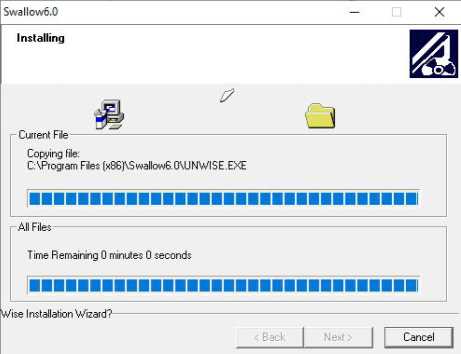 Interface for installing control
SwallowG.O has been successfully installed.
Press the Finish button to exit this installation.
Interface for control installation process
Finish > J
Interface for completing control installation
After the plug-in is installed successfully, refresh the browser to display the preview image.
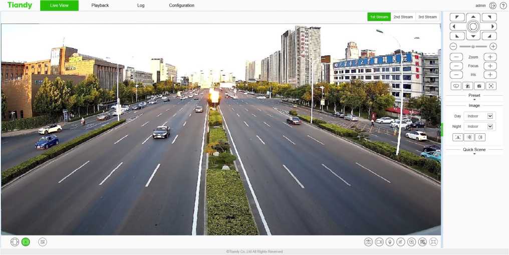
Preview interface
After logging in to the equipment, click the icon at the top of the interface to switch to different interfaces or execute related commands.
| Icon | Description |
| Live View | Click this icon to enter the interface of “Live View”. |
| Playback | Click this icon to enter the interface of “Playback”. |
| Log | Click this icon to enter the interface of “Log”. |
| Configuration | Click this icon to enter the interface of “Configuration”. |
| EW | Click this icon to enter the “EW” interface. (supported by some models) |
| admin | Display the user name for this login. (This icon can only be displayed but not be clicked) |
| Click this icon to log out. | |
| (?) | Click this icon for online help information. (supported by some models) |
After you log in to the system, the prompt box of “change password” will appear in the lower right corner of the desktop. Please click the text in the box, link to the user management interface, select the user, and click “edit”, as shown in the figure below.
Note: In order to ensure the security of your information, please be sure to change the initial
password!
Please change password in time for security,
Change password prompt box
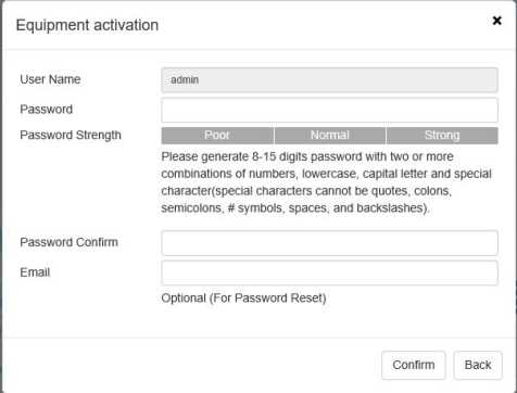
User management interface
After successful login, the system will display the [Preview] interface by default. In other interfaces, users can return to the video preview interface by clicking the [Preview] button at the top of the interface.
Because different models support different functions, the interfaces may also be different, please refer to the actual interface.
Live View
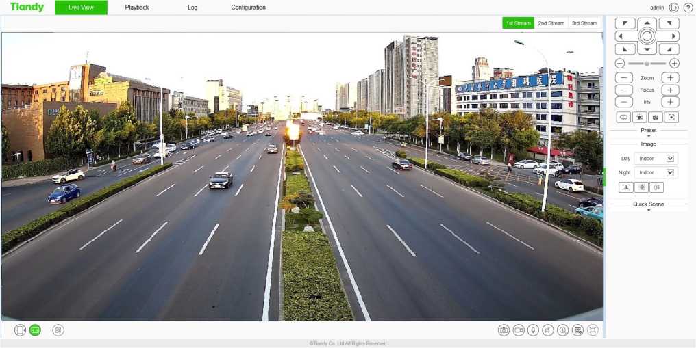
Preview interface
Description:
- Double-click the video to display it in full screen. Double-click again or press the [Esc] key of keyboard to exit the full screen;
- Introduction to the functions of keys at the preview interface:
| Icon | Description |
| 1st Stream | Click “1st Stream”; the video window will display the primary code stream, and the primary code stream will be displayed by default. |
| 2nd Stream | Click “2nd Stream”; the video window will display secondary code stream after selection. |
| 3rd Stream | Click “3rd Stream”; the video window will display third code stream after selection. (supported by some models) |
| o | Click “Fixed Ratio”; the video will be displayed at a fixed scale. |
| I|<b|j | Click “Fit Window”; the video will automatically adapt to the computer resolution display. |
| / □□ \ | QR code button. QR code will appear after clicking it. Users can scan the QR code according to the type of mobile phone and download the mobile client. A third QR code will appear after the equipment is |
| Icon | Description |
| connected to the public network, and you can add the equipment by scanning on the mobile client. (Supported by some models) | |
| Local manual snapshot control button, click enable to snapshot and save the preview picture locally, the storage path of the snapshot file can be modified by itself, the modification page: configuration system settings local settings preview snapshot save path. | |
| Local manual recording control button, click enable, start local recording after enabling, the storage path of recording file can be modified by itself, modification page: configuration – system settings – local settings – saving path of recording file. | |
| ® | Voice intercom switch. When enabled, it can transmit local audio to the front-end equipment through the network for output. |
| @ | Audio preview volume adjustment button, the local output volume can be adjusted by adjusting the slider position. |
| l’ ■<; i | Electronic zoom button. After enabling this function, click the left mouse button to draw the area to be enlarged, and then you can zoom in and view the area. (Supported by some models) |
| Displays the frame rate button. After clicking, the preview interface displays the frame rate information of the current video. Click again to cancel the display of frame rate information. (supported by some models) | |
| Full screen button. Realize full screen preview video, double click left mouse button or press the [Esc] key of keyboard to exit full screen preview video status |
Caution
- All icons are valid when pressed.
- When there is no video in the interface, the audio preview is invalid.
- Talk can only be conducted with one user at the same time, and it is recommended to turn off the
intercom in time after completing the talk, so that others can use it.
 Live View – > control menu
Note: click the arrow or on the right side of the video window to display / hide the control interface.
Live View – > control menu – > Pan/Tilt
This function is only supported by the equipment with 485 control. The functions supported by different models are different, please refer to the actual interface.
| Icon | Description |
| t 7
V |
8 direction keys,press the corresponding direction key to control the pan tilt to rotate in the corresponding direction; the center button is the scan shortcut key, press center button can invoke scan 1. |
| 0 © | The slider can adjust the rotation speed of the device. The closer the “-” end is, the slower the speed is, and the closer the “+” end is, the faster the speed is. |
| — Zoom + | Zoom control button, press “-” control device to perform zoom operation, the field angle becomes larger and the scenery becomes smaller; press “+” control device to perform zoom operation, the field angle becomes smaller and the scenery becomes larger. (this button can also control the electric lens for zooming) |
| ( — j Focus (_ + j | Focus control button, press “-” control device to perform focusing near operation, the near scene is clear and far away fuzzy; press “+” control device to perform focusing far operation, the far scene is clear and near fuzzy. (this button can also control the electric lens to focus) |
| Icon | Description |
| Iris C_L_J | Iris control button, press “-” control device to perform aperture reduction operation, and press “+” control device to perform iris increase operation. (supported by some models) |
| The wiper control button supports the wiper device. Click the button and the wiper will perform an operation. In order to prolong the service life of the wiper, the wiper is equipped with low temperature protection measures, and the function of closing when the ambient temperature is lower than 0 t. | |
| •jfe | Alarm removal button. Alarm can be removed after pressing the button. (Supported by some models) |
| (jb | Flip: control the video image to flip 180 °. |
| Snap button: press the button to turn on the front end interception function. | |
| r n | Key focus, the device automatically completes the focus operation. (supported by some models) |
| Strong light warning button, click enable, the strong light will turn on after enabling, and then click again, the strong light will turn off. (supported by some models) | |
| g>(‘ | Sound warning button. Click “Enable”, and play the alert tone after enabling. (Supported by some models) |
| Display the target information button, click to recognize the face. |
Live View – > control menu – > Preset
Description:
The preset position function is that the device can store the horizontal angle, tilt angle, focal length and other position parameters of the PTZ in the current state into the memory, and can quickly call these parameters and adjust the PTZ and the camera to the position when necessary. Only supported by RS485 controlled cameras. Enter the preset number, and click the Find button to selectthe preset operation, including the[set] and[call]operations.
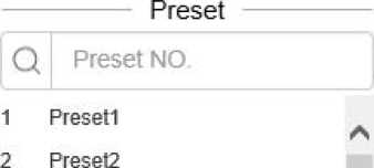
3 Presets
4 Presel4
5 Presets
6 Presets
7 Preset?
8 Presets
9 Presets
10 Presell 0
11 Presell 1
Preset position interface
- Click [Preset]to open or hide the parameter setting page.
- [Set]: Control the PTZ to move to the specified position, enter the preset position number in the blank field, click the button , and then click the button •—:— to add the
corresponding preset position successfully; support to add multiple preset positions.
[Call]: Enter the preset position number in the blank field, click the button , ~ , and then click ‘ ‘I to call the corresponding preset position, and control the PTZ to move to the specified preset
position.
Live View – > control menu – > Image
Image
# 53
□ so
Cl — 50
£5 50
~or](^][ x ipo~
Image parameter setting interface
- Click [Image] to open or hide the parameter setting page.
- Adjust video parameters such as brightness, contrast, saturation and hue by means of
adjusting corresponding slider.
- If you need to restore all video parameters to the default state, you can click the [Restore

Default] button
| # ““ •^— so | Brightness adjustment: adjust the slider position to change the brightness of the image. |
| (J 50 | Adjust the contrast, adjust the slider position to change the image contrast. |
| C — – 50 | Adjust the saturation, adjust the slider position to change the image saturation. |
| 50 | Chroma adjustment: adjust the position of the slider to change the chroma of the image. |
| 01 | Fog transmission function button. Press the button to turn on the fog transmission function. (Supported by some models) |
| jl | Glare suppression function button. Press the button to turn on glare suppression. (Supported by some models) |
| X; | Wide dynamic function button. Press the button to turn on wide dynamic. (Supported by some models) |
| C^) | Restore default button. Button press the video parameter to restore the default value. (supported by some models) |
Live View – > control menu – > Quick Scene
Quick Scene
O Low Ba…Q High Q.
® Self-Ad… O Minim.ii
Quick scene setting interface
Click quick scene to open or hide the parameter setting page. The following can be adjusted through this interface.
| O Low Ba…® HighQ… | According to the specific situation of network environment, choose the appropriate preview mode from [Low Bandwidth] and [High Quality]. |
| ® Self-Ad… O Minimu… | According to the network environment of equipment transmission, two transmission modes can be selected, i.e., [adaptive] and [shortest delay]. In the case of limited network bandwidth, it is suggested to choose adaptive mode to ensure smooth image; in the application environment with high video quality requirements, it is suggested to choose the shortest delay transmission mode. |
| ®TCP 0 UDP 0 MUC | Protocol type: TCP, UDP, muc, use the specified protocol to connect video. (supported by some models) |
Live View – > control menu – > Target Information
When the intelligent analysis mode is [face snapshot], the face information will be displayed in the preview interface.
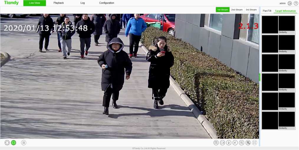
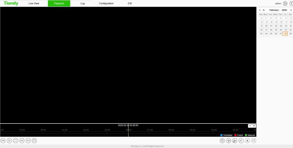
Playback interface
Click [playback] to enter the [playback] interface. In the playback interface, the user can view the video files of the specified date, and can also snapshot and clip the video. See the following table
for basic operation:
| Icon | Description |
| Icon | Description |
| (<K?) | Slow forward button. The speed is 1/2 X, 1/4 X, 1/6 X and 1/8 X. |
| (E) ® | Play / pause button. Click to start/stop playing video file. Double speed playback will be canceled if necessary. |
| © | “Stop Playing” button. You can stop playing the current file by clicking it. |
| (S>) | Fast forward button. The speed is 2 X, 4 X, 6 X and 8 X. |
| Stepping button can playback the video in a single frame. | |
| Browse button, select the video file to play. | |
| Playback snapshot button, saved by default in
C:\Users\jolin\NetVideoBrowser\CapturePicsV |
|
| Playback clip button: Click to start the clip, and click again to finish the clip. The default saving location is C: \ users \ John \ netvideobrowser \ snapshotpictures \. | |
| /T\ w | Clip Management: you can view the type of video clip, video clip progress, current status and other information. |
| @ | Volume adjustment button, the local output volume can be adjusted by adjusting the slider position. |
| Download Management: query or download videos and pictures. | |
| Full screen play button: in full screen mode, double-click the mouse again at any position to exit from full screen mode. | |
| < A January- 2020- ►
Sun Mon Tue Wed Thu Fri Sat 29 30 31 | 1 | 2 3 4 5 6 7 8 9 10 11 12 13 14 15 16 17 18 19 20 21 22 23 24 25 26 27 28 29 30 31 1 |
Select a date in the calendar, double-click the date, and find the qualified file according to the query criteria. |
In the time axis mode, users can drag on the time axis to select and view the video files of the

corresponding time. After selecting the time point, click the play button
to play. The time axis
can be narrowed or enlarged by click
In file mode, users can operate according to file type, video recording type, and whether toquery remotely. The specific functions of buttons in file mode are as follows:
| Icon | Description |
| FileType
Record | v| |
Set the type of file to be queried, such as [Record], [Picture], etc. |
| RecType | Select the type of video file to be queried. (Supported by some models) |
| K | Jump to the first page of query results. |
| « | Go to the previous page of the current page. |
| » | Go to the next page of the current page. |
| >1 | Jump to the last page of query results. |
| Lock: the file can be locked and unlocked. When the disk is full and files need to be deleted, the locked files will not be deleted. | |
| | Start downfo— | Start downloading selected video files |
| Stop Down Io… | | Stop the selected video file being downloaded. |
| j FTP Download | Upload the video file to the FTP server. (Supported by some models) |
| Jump To i | Jump to the specified page. |
| Back | Return to the playback interface. |
| Search | Query: Click to query the corresponding video information. |
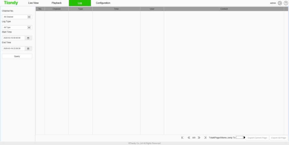
Log interface
Log interface operation instructions
- Select the channel number to query from the [Channel No.] drop-down list.
- Select the type of log you want to query from the [Log Type] drop-down list.
- Select the start date in the [Start Time] drop-down list, and enter the time in the edit box at the back.
- Select the end date in the [End Time] drop-down list, and enter the time in the edit box next to it.
- Click the [Query] button to query the logs within the specified time range.
- When there are many logs, you can use [First Page], [Pre Page], [Next Page], [Last Page] in the lower right corner to turn pages to view the logs, or enter the page number to view directly in [Jump To] to jump to the specified page.
- Click [Export Current Page] to export the log of current page to PC.
- Click [Export All Page] to export all the logs found to the PC.
After login,[ preview ]will be displayed by default. Click [configure] in the menu bar at the top of the page to enter the parameter configuration page, where you can set common settings, audio and video parameters, network settings, intelligent analysis, storage settings and system settings.
Note:
Because different models support different functions, the interfaces and menus may also be different, please refer to the actual interface
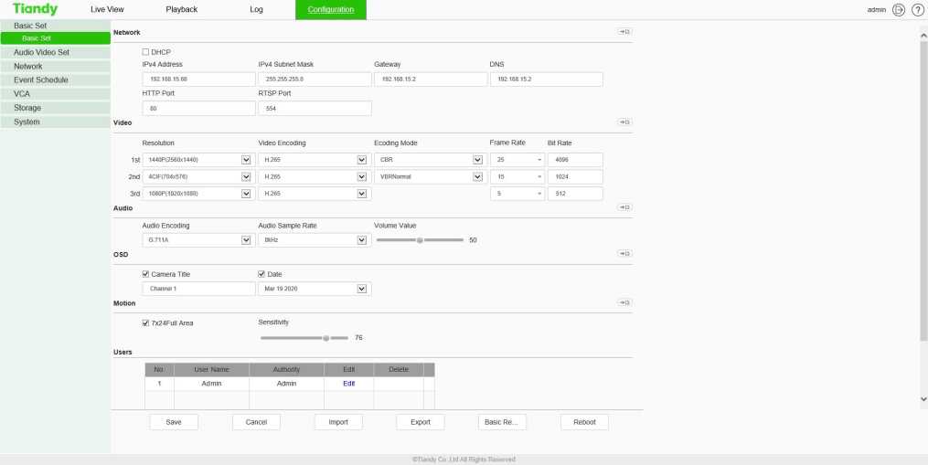
Basic Set interface
Basic Set – > Network
[DHCP]: when checked, the DHCP server will automatically assign IP to the device.
[IPv4 Address]: set the IP address of the device.
[IPv4 Subnet Mask]: set the subnet mask of the device.
[Gateway]: set the gateway of the device.
[DNS]: set the DNS server address.
[HTTP Port]: enter [HTTP port number] in the input box on the page, restart the device, and then modify the HTTP port number.
[RTSP Port]: enter [RTSP port] in the input box on the page, restart the device, and then modify the RTSP port number.
[More…]: Click *D to jump to the network setting interface.
Basic Set – > Video
[Resolution] set the resolution, which is divided into main stream, sub stream and three stream
[Video Encoding] set the video coding mode, which is divided into main code stream, sub code stream and three code streams
[Ecoding Mode] set the coding compression mode, which is divided into main code stream, sub code stream and three code streams
[More…]: Click •——-1 to quickly jump to video settings
Basic Set – > Audio
[Audio Encoding] set the audio coding mode
[Audio Sample Rate] set the audio sampling rate
[Volume Value] set the volume of audio input
[More…]: Click to quickly jump to audio settings
Basic Set – > OSD
[Channel Title] set the character overlay name of the channel. If it is checked, it means display; ifit is not checked, it means display
Set the time and date display format in [Date]. If checked, it means display; if unchecked, it means display
[More…]: Click to quickly jump to character overlay settings
Basic Set – > Motion
Check [7×24 Full Area] to set full time mobile detection alarm
[Sensitivity] set the sensitivity of motion detection
[More…]: Click to quickly jump to mobile alarm
Basic Set – > Users
[New]
To add a new user, you need to set the user name, password and permission. The user name and password can only be entered in English letters and numbers. After the above three items are filled in, click the [Save] button.
Note: only users with administrator rights can add and modify users.
[Edit]
In the user list, click [Edit] to open the password modification prompt box, input the old password, new password and confirm the password, and then click Modify.
[Remove]
In the user list, click [Remove] to open the prompt box and click OK.
Other buttons
Click the [Save] button to save and make it take effect.
Click [Cancel] to restore the last saved parameter.
[Import]/ [Export]: used for equipment maintenance, mainly divided into three categories:
- [Event Server] options include alarm time period and linkage item setting information, excluding intelligent analysis.
- [Smart Analytics] options include settings related to intelligent analysis, including rules, time periods, etc.
- [System Setting] options include all setting information except the above alarm and intelligent analysis, including character superposition, video recording strategy, network setting and other information.
[Basic Reset]: restore the default parameters of the device. (key information such as IP address will not be recovered)
[Reboot]: restart the device.
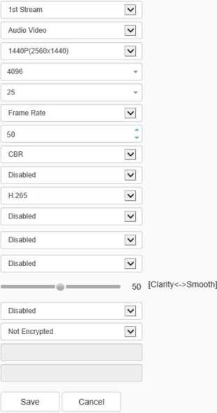
Stream- > Stream
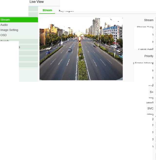

Tiandy
Playback
Log
Basic Set
Key Region
Audio Video Set
Network
Event Schedule
VCA
Storage
System
Video Encoding
Smooth Display Mode
Encrypt Type
Encrypt Password
Password Confirm
Configuration
Smooth Video Streaming
Stream Type
Resolution
Bit Rate
Frame Rate
l-Frame Interval
Ecoding Mode
Corridor Mode
Electronic image Stabilization
Stream – Stream interface
| Parameters | Description |
| Stream | The video related parameters of the main stream, the sub stream and the third stream can be modified. Select the corresponding code stream of the family and modify the parameters of the corresponding code stream |
| Stream Type | You can choose pure video or audio video. |
| Resolution | Set the resolution of the video. (different models are compatible with different maximum resolutions). |
| Bit Rate | Set the bit rate of the video in KB / s. Code rate range: 32 ~ 16384kb / s.
Tip: select the required resolution from the [resolution] drop-down list, and the code stream can be switched to the specified[code rate]. When [compression method] is [constant rate], the [code rate] represents the actual code rate of the code stream; when [compression method] is [variable rate], the [code rate] represents the maximum allowed code rate of the code stream. |
| (Different models support different code rates, please refer to the actual interface) | |
| Frame Rate | Sets the frame rate of the current video. In the [PAL] system, some models support 50 frames, and the maximum support is 25 frames when the wide dynamic mode is turned on. [NTSC] under the system, some models support 60 frames, and when the wide dynamic mode is turned on, the maximum support is 30 frames. |
| Priority | The video set to [frame rate first] is smoother and the video set to [quality first] is clearer. |
| I-Frame Interval | The number of frames between every two I frames can be set, and the range can be 10-100. |
| Ecoding Mode | Set constant rate or variable rate compression. At the fixed bit rate, the amount of video data fluctuates little, and the bandwidth occupied by the network transmission is stable; at the variable bit rate, the amount of video data changes with the complexity of the video picture, and the bandwidth is saved when the scene is single. In the case of variable bit rate, there are several levels. If the better, the higher the average bit rate is. |
| Corridor Mode | The screen is rotated 90 degrees to adapt to the scene where the device is installed on the wall. It is off by default. |
| Video Encoding | Set how video is encoded. H. 265 encoding saves bandwidth, but some browsers or playback software do not support h.265. |
| S+ | Switch S + on and off can be selected from the drop-down list. When S + is enabled, functions such as compression mode, video quality, I-frame frame rate and key area will not be available. |
| Electronic Image
Stabilization |
According to the actual situation, user can select [On] or [Off] to optimize the picture quality and prevent shake. (Supported by some models) |
| SVC | When [SVC] is turned on, P frame can be encoded as non reference frame, which can be used for frame extraction video recording and save storage space. The video file after frame extraction still supports normal decoding. When the [auto] mode is selected, the device will adapt to the current network environment and decide whether to send the frame to ensure that the image can be previewed normally during preview. (supported by some models) |
| Smooth Video
Streaming |
The ratio of I frame and P frame can be set. The closer to smoothness, the better the smoothness of dynamic scene, the closer to clarity, and the better the video clarity performance of static scene. |
| Smooth Display
Mode |
Set whether to turn on unobstructed mode. (supported by some models) |
| Encrypt type | According to the situation, users can encrypt video data to improve the security of network transmission. [Encrypt type] select the required encryption algorithm (currently only AES algorithm is available), [Encrypt password] set the encryption password, and [password confirmation] input the encryption password again to ensure that the password entered twice is the same. Click [Save] to take effect. |
After setting, click Save to take effect. Click [reset] to restore the last saved parameter.
Stream – > Key Region
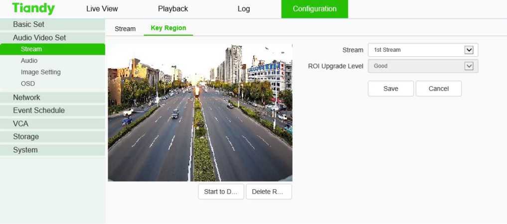
Video parameters key area interface
After the front-end connection supporting the key area setting, you can set the key area here. The image quality displayed in the focus area is higher.
- Click the “Start to Drawing” button to drag the video by holding down the left mouse button, and then you can set the key area. Several key areas can be set up. Click “Delete Area” to delete all the key areas that have been set.
- Click [Save] to save the corresponding parameter settings. Click [Cancel]to restore the last saved
parameter.
| Parameters | Description |
| Stream | Set the bitstream of the application focus area. |
| ROI Upgrade Level | Set the promotion level of videos in key areas. |
Tiandy
| Basic Set | Audio | ||
| Audio Video Set | |||
| Stream | Audio Encoding | G.711A 0 | |
| Audio | Audio Sample Rate | 8kHz v| | |
| Image Setting | |||
| OSD | Audio Control Type | Lineln v| | |
| Network | Volume Value | ||
| 50 | |||
| Event Schedule | Audio Output Type | Built-in speaker v| | |
| VCA | Volume Value | ||
| Storage | |||
| Audio Denoising | |||
| System | |||
| Echo suppression | Disabled v| | ||
| Save Cancel |
Live View
Playback
Configuration
Interface of audio parameter setting
| Parameters | Description |
| Audio Encoding | Set the audio encoding mode of the bitstream. |
| Audio Sample | Sets the audio sampling rate for the bitstream. |
| Rate | It supports two modes: linein and micin. The control mode needs to be selected according to the output signal amplitude of the external audio equipment. When the |
| Audio Control | external mic small signal (mv level signal) is connected, please select micin; when the |
| Type | external equipment is the active audio equipment (V level signal), please select linein mode. (supported by some models) |
| Parameters | Description |
| Volume value | The output sound size can be adjusted, and the adjustment range is 0-100. The smaller the value is, the smaller the output audio signal amplitude of the device is; the larger the value is, the larger the output audio signal amplitude of the device is. |
| Audio Denoising | The filter level of environmental noise can be set. The default level is 1. When the
value is 0, turn off the audio noise reduction function. (supported by some models) |
| Audio Output
Type |
The audio output type includes built-in speaker, external sound source and off. When the built-in speaker is selected, the output volume can be adjusted. (supported by some models) |
| Echo Suppression | Turn on to improve the quality of audio intercom. (supported by some models) |
After setting, click Save to take effect. Click [reset] to restore the last saved parameter.
Note:
- To modify the audio parameters, the intercom function needs to be turned off.
- Modify the audio coding mode and audio sampling rate parameters.
Image Settings – > Image
The applications of HD parameters are reflected in the form of templates, and the system provides several sets of commonly used templates for use. The HD parameters of each template are independent of each other, and the parameters of the second template will not be affected after modifying the HD parameters of the first template, so please confirm the current template before modifying the parameters.
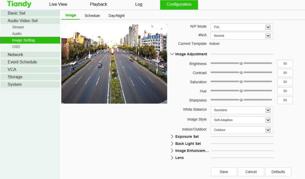
Image interface
Image – Template Selection
In[Current Template], select the template to modify the parameter. In [ template name], you can define the template name
Image -Image Adjustment
Click next to [Image Adjustment] to expand the[Image Adjustment] interface. The user can set the brightness, contrast, saturation, hue, sharpness, white balance, image style and indoor/ outdoor modes of the picture through the image adjustment menu.
Image -Exposure Set
Click the button next to [Exposure Set] to expand the [Exposure Set] setting interface.
| Parameters | Description |
| Shutter speed | You can set the maximum exposure time allowed to affect the brightness of the image. If the exposure time is too long, the moving image will be dragged, and if the exposure time is too short, the video picture will be darker. |
| Automatic gain | The maximum gain allowed can be set to affect the brightness of the image. Too much gain may produce more noise. |
Image -Back Light Set
Click the “ ” button next to [Backlight] to expand the [Backlight] setting interface.
| Parameters | Description |
| HLC | It is mainly used in road monitoring scenes.
It can suppress the glare such as car headlights after being turned on, thus reducing the effect of glare. |
| Super-Wide dynamic
Grade |
In the drop-down list, there are [off], [ultra wide dynamic auto], [ultra wide dynamic manual] and backlight compensation options.
Select [ultra wide dynamic auto] or [ultra wide dynamic manual] to display the [ultra wide dynamic] slider. Drag the slider to set the wide dynamic level that meets the requirements of the scene. The larger the value, the more obvious the effect. Select [backlight compensation] and check [set backlight compensation area] and click Save to set light compensation and improve the brightness in the setting area |
Image – Image Enhancement
Click the button next to [Image Enhancement] to expand the [Image Enhancement] setting interface.
| Parameters | Description |
| Defog | Select [Enabled], [Disabled] and other options according to actual needs. |
| Digital Noise
Reduction |
In the drop-down list, you can select [close], [normal mode] and [expert mode]. Select [normal mode], display the [noise reduction level] slider, drag the slider to set the noise reduction level. Select [expert mode], and the sliders of[ airspace noise reduction level] and [time domain noise reduction level ]will pop up respectively. Drag the two sliders to set [airspace noise reduction level] and [time domain noise reduction level] respectively. |
Note:
After the HD parameters are set, click[Save] to save. Click [Cancel] to restore the last savedparameter. [Defaults]: the parameters of each template can be restored to the default settings.
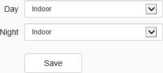
Image settings – > Schedule
Tiandy Live view
Basic Set
Audio Video Set
Stream
Image
Playback Log
Schedule Day/Night
Configuration
Audio
Image Setting
OSD
Network
Event Schedule
VCA
Storage System
Schedule interface
Users can use different templates for equipment at different time periods by means of using HD template, to ensure that the effects of videos are the best in different time periods.
[Day]: Set the HD template during the day.
[Night]: Set the HD template at night.
Click the [Save] button to save and make it take effect.
Image settings – > Day/Night
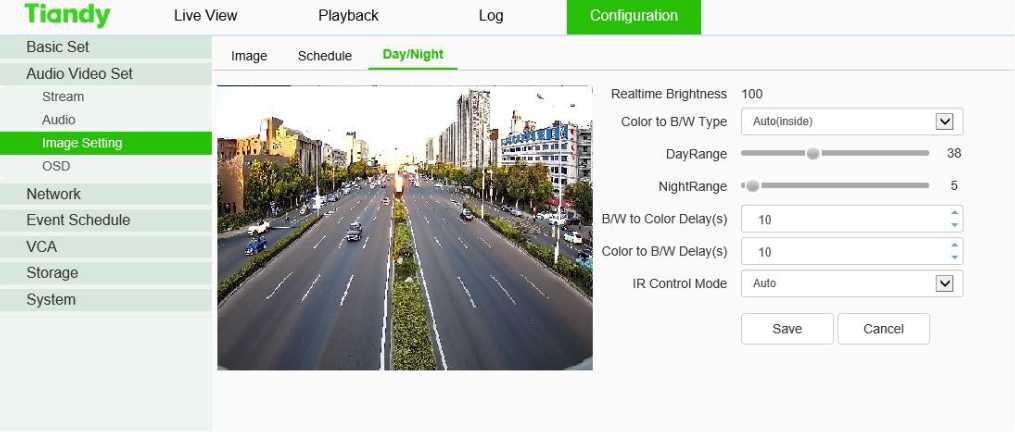
Day/Night setting interface
In the color to black interface, set the device to switch to day or night mode according to the
specified conditions, and set the fill light.
[Color to B/W Type]: allows [device] to switch between day and night modes according to different rules. Because the functions of different models are different, please refer to the actual interface.
[Auto(inside)]: in the internal synchronization mode, the [device] will automatically detect the brightness of the video screen. When the video brightness is higher than the brightness value in the day, the video will change from black to color. When the video brightness value is lower than the brightness value at night, the video will change from color to black. The [real-time brightness value] above the page is the detected current brightness value.
[B/W]: the device video is always in black and white mode.
[Color]: the device video is always in color mode.
[Auto(outside)]: detect the brightness of the external environment through the photoreceptor. When the external brightness is higher than the brightness value in the day, the video changes from black to color. When the external brightness is lower than the brightness value at night, the video changes from color to black.
[Schedule]: in timing mode, you can specify the daylight time and dark time.
[Adaptive]: the device automatically switches between black and white or color mode according to the scene.
[Sensitivity]: toggle the drop-down box to select sensitivity.
[IR lamp control mode]: set the IR lamp on mode.
[Brightness of IR lamp]: slide the slider to set the brightness value of IR lamp. The maximum value is 100.
[White Light Control Mode]: set the white light on mode.
[Brightness of White Light]: slide the slider to set the brightness value of white light. The maximum value is 100.
Click the [Save] button to save and make it take effect.
Click [Cancel] to restore the last saved parameter.
OSD – > OSD
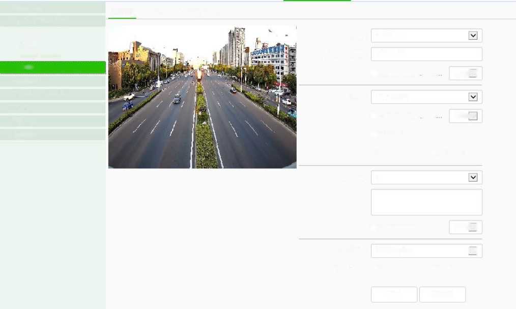
Basic Set
Audio Video Set
Stream
Audio
Image Setting
Network
Event Schedule
VCA Storage System
OSD LOGO Privacy Mask
□ Customized L… C… Whitipy]
Stream 1st Stream
SI Camera Title Channel 1
□ Customized L… C.
□ Customized L… C White iv
□Show Week
@24 hours 012 hours
White fv|
HDate Mar 19 2020
Additional 1
OSD Size Self-Adaptive j v|
Fonts Type ©Vector O Lattice
Save Cancel
OSD
Interface of OSD
[Stream]: select the code stream to stack character information.
[Channel Title]
- Select the [Channel Title]] check box to overlay the channel name on the screen.
- Enter a name in the input box on the right to set the channel name.
- From the [Color] drop-down list, select the color you like for the superimposed content.
- If you need to change the position of the superimposed character, select the [user defined position] check box, and click on the small screen with the mouse to specify a new position for the superimposed character.
[Date]
- Select the [Date] check box to overlay the date and time on the picture.
- Select your preferred date format from the drop-down list on the right.
- If you need to include the week in the displayed time and date, select the[Show Week] check box.
- As required, the time can be displayed in 24-hour or 12-hour mode. Select the corresponding option from the 2 buttons below.
- From the [Color] drop-down list, select the color you like for the superimposed content.
- If you need to change the position of the superimposed character, select the [user defined position] check box, and click on the small screen with the mouse to specify a new position for the superimposed character.
[Additional]
- [Additional] at present, there are 5 areas for stacking.
- Input the text content to be superimposed from the input box below, including Chinese characters, English and common punctuation marks. You can stack multiple lines of content in one area as needed. Some models support peripheral mode. Click [insert] to add peripheral information.
- From the [color] drop-down list, select the color you like for the superimposed content.
- Select the [user defined location] check box and click on the small screen with the mouse to specify a new location for the superimposed characters.
[OSD Size]
You can specify the size of the superimposed characters, select the preferred character size (unit: pixel) in the [OSD Size] drop-down list, or select [Self-Adaptive] to let the system automatically adjust the character size.
After all the above parameters are set, click [Save ]to save and take effect; click [Cancel]to restore the last saved parameters.
OSD – > LOGO
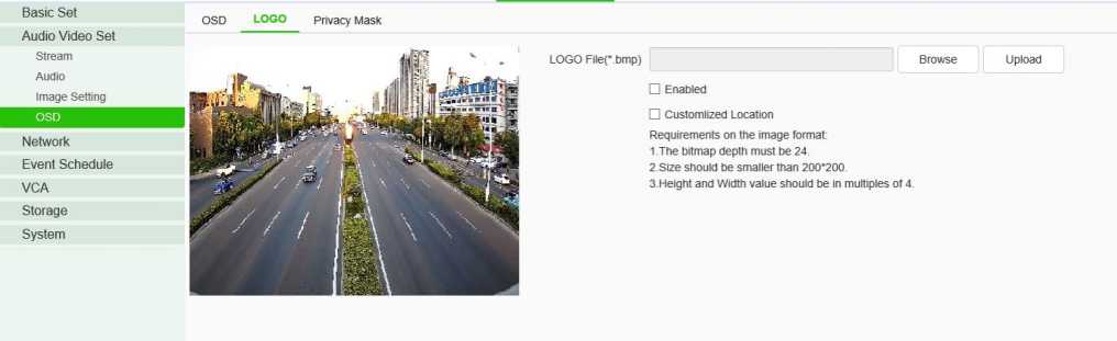
LOGO setting interface
- Enter the path of the image file in the [LOGO File] input box, or click the [Browse] button to find the image file in the pop-up window.
- After clicking the [Upload] button, the picture will be uploaded to the equipment, and the 83
equipment will restart automatically after uploading the picture.
- After the equipment is restarted, select the [Enable] check box to overlay the LOGO picture on the video. If the [Enable] check box is canceled, the LOGO will not be displayed.
- With [Enable]selected, select the [Customlized Location]check box and click on the video screen with the mouse to specify a new display location for the LOGO.
Note:
- The LOGO picture must be a bitmap file in bmp format. The bitmap depth is 24, the size is smaller than 200 * 200 pixels, and the height and width are divisible by 4. Please use a picture that meets the requirements.
- Overlapped LOGO will automatically remove its black and white background.
OSD- > Privacy Mask
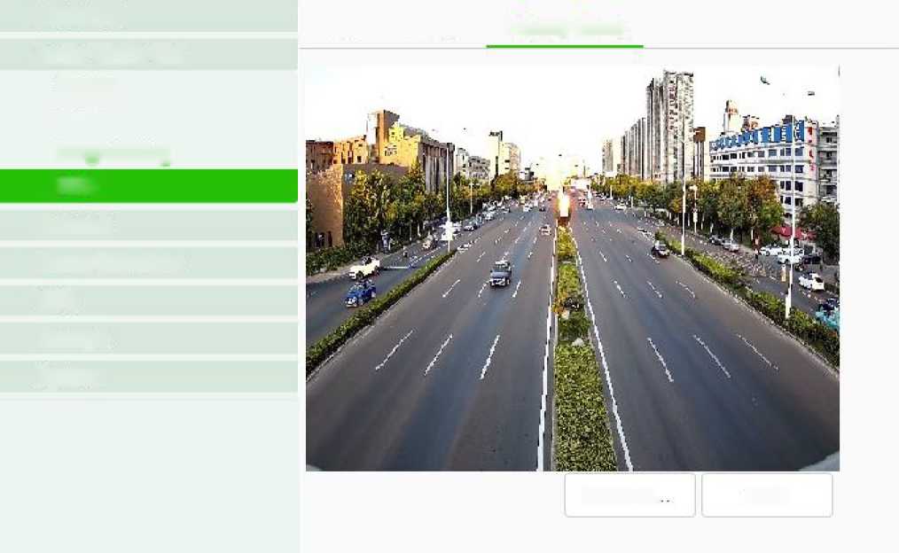
Delete R.
Basic Set
Audio Video Set
Stream
Audio
Image Setting
Network
Event Schedule
VGA
Storage
System
OSD LOGO Privacy Mask
Save
OSD
Privacy Mask setting interface
According to the user’s needs, the occlusion area is set on the video screen to protect the privacy information and support multiple occlusion areas.
- Drag the mouse to draw the occluded area on the video screen, allowing to draw multiple
occluded areas.
- If you need to delete the drawn area, click [Delete Region] to delete all the occluded areas, so as
to draw again.
- Click[ save] to save and take effect.
Basic set – > TCP / IP
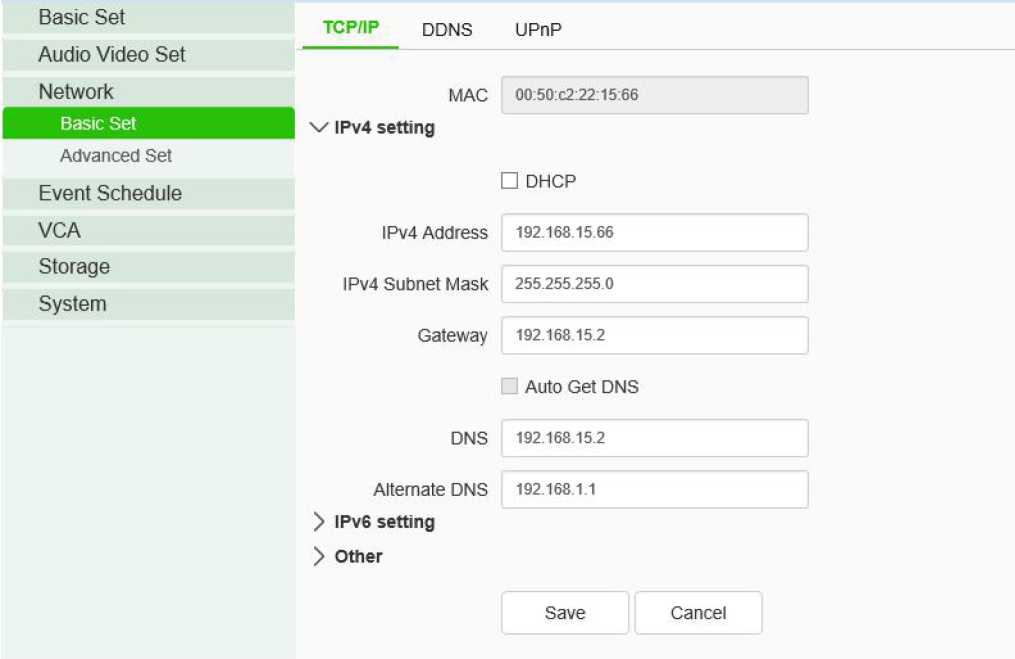
TCP / IP setting interface
[DHCP]: set whether the DHCP server automatically assigns IP to the device.
[IPv4 Address]: set the IP address, subnet mask and gateway of the device.
[IPv6 Address]: this device supports IPv6. Users can see the IPv6 address and subnet mask of the device on the page.
[DNS]: set the DNS server address.
[MAC]: displays the physical address of the device.
[MTU]: set the size of MTU, ranging from 500 to 1500, and the default is 1500. After setting, click Save to save the setting, and it will take effect after restarting the equipment.
[HTTP Port]: enter [HTTP port number] in the input box on the page, restart the device, and then modify the HTTP port number.
[RTSP Port]: enter [RTSP port number] in the input box on the page, restart the device, and then modify the RTSP port number.
[HTTPS Port]: enter [HTTPS port number] in the input box on the page, restart the device, and then modify the HTTPS port number.
[RTSP Path]: refer to the example path in the interface. Check enable intranet search to enable this function.
[Save]: save the current settings.
[Cancel]: restores the last saved parameter.
Basic Set – > DDNS
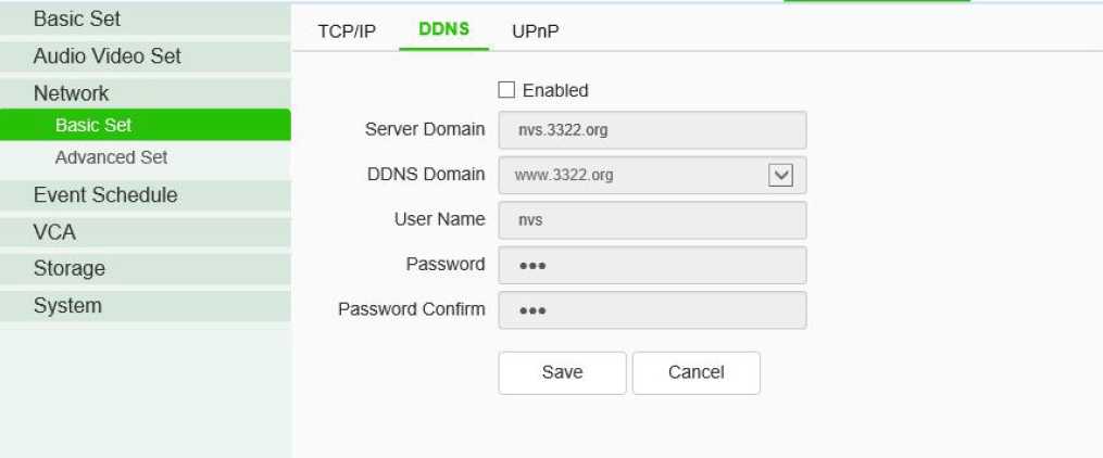
DDNS setting interface
After checking [Enabled] DDNS, select the [server address] to be set, modify equipment [Server Domain], set [DDNS Domain], [User Name], [Password ]and[Password Confirm ], and then click [Save ] to set DDNS network server information. Click [Cancel] to restore the last saved parameter.
Basic Set- > UPnP
TCP/IP DDNS URnP
| Audio Video Set
Network |
□ Enabled | |||||
| Mapping mode of the… | Manual | □ | ||||
| Advanced Set
Event Schedule VCA Storage System |
||||||
| Port Type | External Port | External IP Address | Internal Port | State | I | |
| HTTP | 0 | O.O.O.O | 80 | Not activated | ||
| RTSP | 0 | O.O.O.O | 554 | Not activated | ||
| Data Port | 0 | o.o.o.o | 3000 | Not activated | ||
| HTTPS | 0 | o.o.o.o | 443 | Not activated | ||
| RTMP | 0 | o.o.o.o | 1935 | Not activated |
| Save | Cancel |
UPnP interface
Only when port mapping is enabled, can the ports of network devices be opened normally. Port mapping methods include automatic and manual.
- When “Auto” mode is selected and UPnP is enabled, users do not need to do port mapping on the router, only need to turn on the UPnP function on the router.
- Select “Manual”, the user needs to manually map the port on the router. In manual mode, the user can specify the external port to be mapped under the public IP. The user does not need to modify the port of the network device itself. If the router or gateway does not support the UPnP function, the user can fill in the current mapped external port status here.
- After the port mapping, the status column will show whether it is effective. At the same time, the external port under the currently mapped public IP will be displayed in the external port. If users need to access network devices through the public network, they need to use the currently mapped external port to access.
[Save]: save the current settings.
[Cancel]: restores the last saved parameter.
Advanced Set – >IP Filter
| Email PPPoE SIP Multicast QoS Settings Access Platform | ||||||||
| ® No Limit O White list | O Blacklist | |||||||
| i n | Add | Delete | ||||||
| |D | No. | IP | ||||||
| Save | Cancel | |||||||
IP Filter setting interface
IP firewall, also known as black-and-white list, is provided for users to manage access rights more flexibly.
[No Limit]: select the[No Limit] button to remove the restriction of the black and white list. All IP addresses can be accessed, not only the IP addresses in the list.
[Whitelist]: if you want to allow only a few trusted IPS to access the device, you can select the [Whitelist] button, enter the trusted IP addresses one by one, click [Add] to add to the list, and then click [Save] to make the whitelist effective. At this time, only a number of IPS specified in the list can successfully log in to the device, and login requests from other IPS will be rejected, regardless of whether their user name and password are correct or not. Users can specify up to 16 trusted IP addresses in the white list.
Note: when adding the white list, please confirm whether to add the IP address of the current user. [Blacklist]: if you want to block some IP addresses and prohibit them from accessing the equipment,you can select the button of[ blacklist], input the IP addresses you want to block one by one, click [Add]to add them to the list, and then click [Save] to make the blacklist effective. At this time, the login request from any IP in the list will be rejected, regardless of whether its user name and password are correct or not.
Note: when adding the blacklist, please confirm whether the IP address of the current user is added. [Delete]: if you need to delete some IPS from the list, just select the check box on the left of these IPS and click [delete]. Note that all IPS cannot be deleted when deleting the white list, otherwise the device will not be able to log in successfully.
Note: IP filtering can only be judged when a user is newly logged in, and cannot filter the logged in IP. It is strongly recommended to restart the device in time after each blacklist configuration to shield the illegal IP address.
[Save]: save the current settings.
[Cancel]: restores the last saved parameter.
Advanced Set – > Email
IP Filter Email pppoE SIP Multicast QoS Settings Access Platform
Email Server
Port
Email Account
Email Password
Email Mode
Encryption
Email Subject
Main Email Address
Email Address 1
Email Address 2
Email Address 3
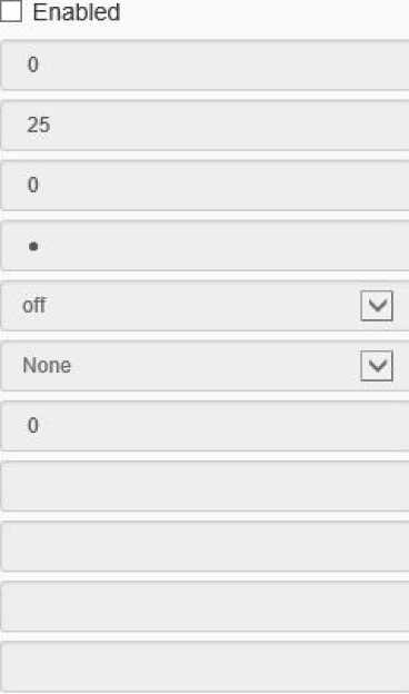 Save Test Cancel
Mail setting interface
After the user enables mail, the alarm server will automatically send alarm mail to the mailbox address set by the user when an alarm occurs.
- The email server address input format is smtp.xx.com, where XX represents the email server and is the login email of the account, for example, smtp.163.com.
- The account and password are the user name and password of the login SMTP server mailbox.
- The encryption mode can be none, SSL or TLS.
- After setting the subject and CC email address, click[test ]to test whether the mail server function is normal. Click [save] to save the current settings. Click [reset] to restore the last saved parameter.
Advanced Set – > PPPoE
IP Filter Email PPPoE SIP Multicast QoS Settings Access Platform
□ Enabled
User Name 1234567S
Password •*»•••»•
Password Confirm ••••••••
Save Cancel
PPPoE setting interface
After enabling the [PPPoE] function, change the [User Name],[ Password ]and [Password Confirm], and [Save] to set the PPPoE network server information, which will take effect after restart;[Cancel]to restore the last saved parameters. (supported by some models)
Advanced Set – > SIP
IP Filter Email PPPoE SIP Multicast QoS Settings Access Platform
Server IP
Server Port
Server ID
Device ID
User Name
Password
RegValidity
Keep-Alive
Heartbeat Interval
Heart Rate
Channel No.
Channel ID
Channel Level
PTZ Time
Event Input
Event Input No.
Event Level
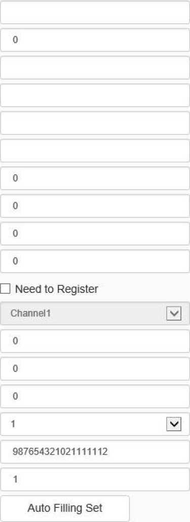 Cancel
Save
SIP setting interface
The SIP protocol can be accessed to other platforms by setting corresponding parameters.
[Auto Filling Set]: click this button, the channel number and alarm input number will be increased and set from the current channel number.
[Save]: save the current settings.
[Cancel]: restores the last saved parameter.
Advanced Set – > Multicast
IP Filter Email PPPoE SIP Multicast qos Settings Access Platform
□ Enabled
IP Address [224 0 0 0-239.255.255.255]
Port 0
Save Cancel
Multicast setting interface
Input the multicast [IP Address] (range: 224.0.0.0-239.255.255.255), input the port number
(range: 1-65535), and click Save to restart the device. (supported by some models)
Advanced Set – > QoS settings
IP Filter Email PPPoE SIP Multicast QoS Settings Access Platform
Audio/Video DSCP o
Event DSCP o
Save Cancel
QoS setting interface
[Audio/Video DSCP] input the DSCP parameters in the input box, disconnect and reconnect the video stream parameters to take effect, and [Event DSCP] input the DSCP parameters in the input box, and click [Save] to save the parameters. (supported by some models)
Advanced Set – > Access Platform
IP Filter Email PPPoE SIP Multicast QoS Settings Access Platform
✓ Platform Enabled
IZOnvif f/l All owed H265 video access
13 P2P
13 RTS P
Save Cancel
Platform access setting interface
[Platform Enabled]
Support the enabling and shutting down of onvif, RTSP, P2P and CGI. After setting, some devices will restart automatically and take effect.
Note: to replace the access platform, you need to first disable the enabled platform, and then select a new platform and enable it.
[Auto Filling Set]: click this button, the channel number and alarm input number will be increased and set from the current channel number.
[Save]: save the current settings.
[Cancel]: restores the last saved parameter.
Event management – > Event Input
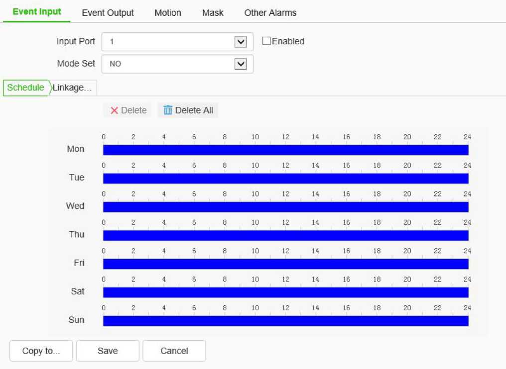
Event input setting interface
Set port event detection related parameters.
- Select the input port, check the [Enable] check box to enable the port alarm detection function, and uncheck to turn off the port alarm detection function.
- [Mode Set] set normally open and normally closed, where [NO] refers to the alarm when the disconnected line is short circuited, and [NC] refers to the alarm when the connected line is disconnected.
- The user can set the [Schedule] as required, and only detect the alarm within the set date and time period.
- Set [Linkage Mode]to realize the alarm linkage after triggering the alarm, such as[Common link], [Alarm Output], [Link Snap],[ l PTZ linkage channel], etc.
- Click [Save] to save the corresponding parameter settings, and click [Copy to…] copy the parameters of the current port number to other port numbers. Click [Cancel]o restore the last saved parameter.
Note: alarm input and alarm linkage output are limited to products that support alarm input and alarm output functions.
Event Management – > Event Output
Event Input Event Output Motion Mask Other Alarms
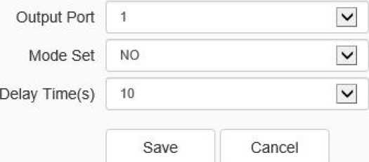
Event output setting interface
The user can select two modes to set:[NO] and[ NC]. Select the output port, set the port alias, select the mode setting, and select the alarm elimination mode. You can set the delay time of the alarm state through [Delay Time(s)].
Click [Save] to save the corresponding parameter settings, and click [Copy To…] copy the parameters of the current port number to other port numbers. Click [Cancel] to restore the last saved parameter.
Event Management – > Motion
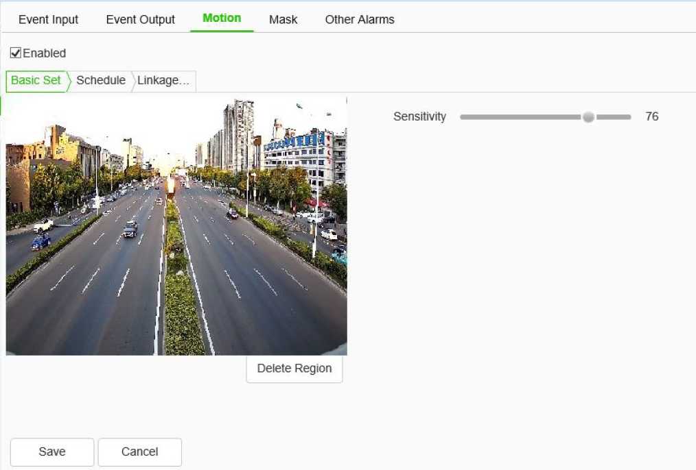
Motion setting interface
The user sets the mobile alarm area. When there is an object moving in the setting area, the video preview interface will prompt the video mobile alarm, and the corresponding alarm linkage will be carried out according to the setting.
- The mobile alarm detection function is enabled by default. Drag the left mouse button in the video screen to draw the area to detect the mobile alarm. Click [Delete Region] to delete the mobile alarm detection area.
- Set the mobile alarm sensitivity, the higher the value, the more sensitive the mobile alarm detection.
- The user can set the [Schedule] as required, and only detect the alarm within the set date and time period.
- Set [Linkage Mode] to realize the alarm linkage after triggering the alarm, such as [Alarm Output], [Linkage Snap], etc.
- Click [Save] to save the corresponding parameter settings, and click [Copy To…] copy the parameters of the current port number to other port numbers. Click [Cancel] to restore the last
saved parameter.
Event Management – > Mask
Event Input Event Output Motion Mask Other Alarms
□ Enabled Sensitivity 50
Schedule ^Linkage… X Delete ®j Delete All 0 2 4 6 8 10 12 14 16 18 20 22 24
Mon |§
0 2 4 6 8 10 12 14 16 18 20 22 24
Tue 0 2 4 6 8 10 12 14 16 18 20 22 24
Wed 0 2 4 6 8 10 12 14 16 18 20 22 24
Thu 0 2 4 6 8 10 12 14 16 18 20 22 24
0 2 4 6 8 10 12 14 16 18 20 22 24
Sat 0 2 4 6 8 10 12 14 16 18 20 22 24
Save Cancel
Mask setting interface After the occlusion alarm is turned on, when the image in the video screen is blocked, the alarm situation will be detected according to the sensitivity.
- Check the [Enable] check box to turn on the video blocking alarm detection function, and uncheck to turn off the video blocking alarm detection function.
- Set the video occlusion alarm sensitivity, the higher the value, the more sensitive the video occlusion alarm detection.
- The user can set the [Schedule] as required, and only detect the alarm within the set date and time period.
- Set the [Linkage Mode] to realize the alarm linkage after triggering the alarm, such as [Alarm Output], [Link Snapshot], etc.
- Click [Save] to save the corresponding parameter settings, and click [Copy To…] copy the parameters of the current port number to other port numbers. Click [Cancel] to restore the last 98
saved parameter.
Event Management – > Other Alarms
Some models support abnormal alarm. For exception types, you can select [Disk Full], [Disk R/W Error], [IP Address Conflict], [MAC Address Conflict], and set [Common Link] and [Alarm output].
In [Common Link ], you can set [Send To Server ]and [Send Email]. ([IP Address Conflict] and [MAC Address Conflict] cannot be set.)
[Alarm Output] the alarm output port number can be selected.
Alarm management – > mail alarm
Some models support email alarm. After the user enables email alarm, the email server will automatically send the alarm email to the email address set by the user when an alarm occurs.
Some models support a variety of application modes, such as [face capture], [intelligent monitoring] and so on. When an application mode is selected from [Allocation of resources] menu, the corresponding intelligent analysis’ parameters will be set.
[Capture facial images]: When the algorithm finds a person’s face in the video, it captures the image and saves it to the preset location.
[Smart surveillance]: Common monitoring mode includes intelligent algorithms such as behavior analysis, crowd gathering, video diagnosis and audio anomaly detection, etc.
Basic Set
Audio Video Set
Dome Set
Network
Event Schedule
VCA
Allocation of resources
Advance Params
Online VCA Log
Storage
System
Create Rule
□ Enabled
Event Set
Save Cancel
Mar 19 2020 15:07:43
Create Rule
Interface of Create Rule setting
[Enable]: enables or disables the intelligent analysis function of the current channel.
[Event set]: the device supports a variety of algorithms, such as behavior analysis, crowd aggregation, face detection, number of people statistics, and on duty detection, which are mutually exclusive. Only one of them can be enabled. Some devices support face detection, population statistics, on duty detection algorithm, video diagnosis, audio anomaly detection, etc.
Description:
- Different models support different algorithms. Please refer to the actual interface.
- Some algorithms are mutually exclusive with others. Other algorithms can be enabled simultaneously. Please refer to the actual interface.
- Select the corresponding algorithm in [event type] and set the parameters of the algorithm.
[Event Selection] = > [Behavior Analysis]
[Behavior Analysis]: the algorithm includes 10 specific algorithms, including trip line, double trip line, perimeter, item left behind, item lost, wandering, running, parking, alert, heat map. Eachalgorithm can be repeatedly enabled and configured with different parameters, but the total rule cannot exceed 10. After setting, click save, and then click next to configure [Event Schedule]. See [Event Schedule] for details.
[Event Type] = > [Behavior Analysis] = > [Tripwire]
Create Rule
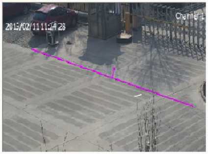
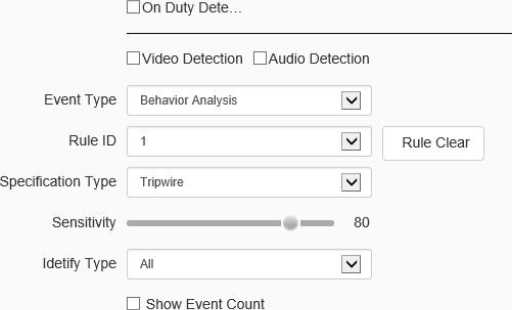
H Enabled
[Event Set^ Schedule Linkage…
Start to Draw Line Clear
SSBehavior Anal… □Demographics □ Crowd Detection
Event Selection
□ Show Event Rule
□ Two-way Event
0 Display Target
Save
Next
Cancel
Tripwire setting interface
- Select the rule number, set the event as trip wire, and check [Enable] to enable the rule.
- Draw a rule line, and indicate the direction in which it is forbidden to cross with the arrows on the rule line.
- Set whether to display alarm statistics, display alarm rules, two-way alarm and display target.
- Click save after setting.
[Event Type] = > [Behavior Analysis] = > [Double Tripwire]
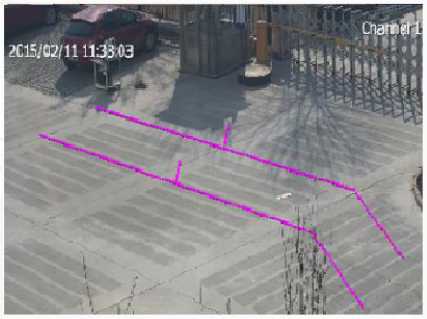
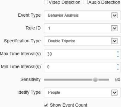
0 Enabled
| Event Sety Schedule Linkage.
Start to Draw Line Clear
Event Selection
0Behavior Anal… □Demographics □ Crowd Detection
□ On Duty Dete…
Rule Clear
0 Show Event Rule
0 Two-way Event
□ Display Target
Save
Next
Cancel
Double tripwire setting interface
- Select the rule number, set the event as double trip wire, and check [Enable] to enable the rule.
- Draw 2 rule lines, and indicate the direction in which it is forbidden to cross with the arrows on the rule line. The directions of the 2 rule lines should be the same. An alarm will be issued when crossing two lines continuously within the specified time.
- Set the maximum and minimum time intervals, which means the time range of crossing two rule lines consecutively.
- Set whether to display alarm statistics, display alarm rules, two-way alarm and display target.
- Click save after setting.
[Event Type] = > [Behavior Analysis] = > [Perimeter]
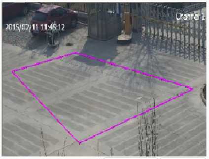
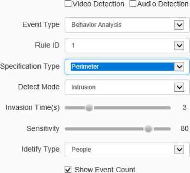
H Enabled
| Event Sep Schedule Linkage.
Start to Draw
Line Clear
Event Selection
0Behavior Anal… □Demographics □ Crowd Detection
□ On Duty Dete.
Rule Clear
S Show Event Rule
□ Display Target
Save
Next
Cancel
Perimeter setting interface
- Select the rule number, set the event as the perimeter, and check [Enable] to enable the rule.
- Draw the perimeter detection area.
- Select the detection mode. In entry mode, an alarm will be triggered in the area where the target entered; in leaving mode, an alarm will be triggered in the area where the target left; in intrusion mode, an alarm will be triggered when the target is kept in the detection area for the time specified for intrusion.
- Set the intrusion time, which means that an alarm will be triggered when the target is kept in the detection area for the time specified.
- Click save after setting.
[Event Type] = > [Behavior Analysis] = > [Object Abandone]
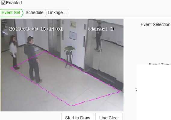
□ On Duty Dete…
Event Type
Rule ID
Specification Type
Event Time(s)
Sensitivity
0Behavior Anal… □Demographics OCrowd Detection
□Video Detection DAudio Detection
5
85
0 Show Event Count
H Show Event Rule
□ Display Target
Save
Next Cancel
Object Abandone setting interface
- Select the rule number, set the event as item left, and check [Enable] to enable the rule.
- Draw the item left detection area. When the item left and item lost are enabled simultaneously, the detection areas should not overlap.
- Set the alarm time: indicate that an alarm will be triggered when the target is kept in the left state in the picture for the time specified.
- Click save after setting.
[Event Type] = > [Behavior Analysis] = > [Missing Objet Detection]
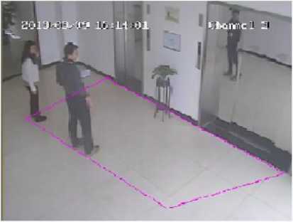
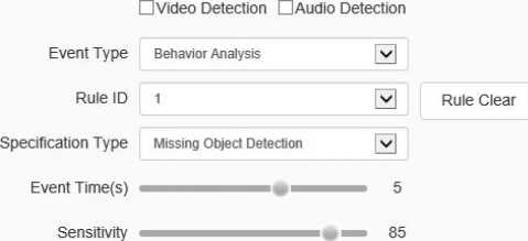
SI Enabled
Event Set \ Schedule Linkage. .
Start to Draw Line Clear
Event Selection
H Behavior Anal… □Demographics □ Crowd Detection
□ On Duty Dete…
S Show Event Count
H Show Event Rule
□ Display Target
Missing Object Detection interface
- Select the rule number, set the event as item lost, and check [Enable] to enable the rule.
- Draw the item left detection area. When the item lost and item left are enabled simultaneously, the detection areas should not overlap.
- Set the alarm time: indicate that an alarm will be triggered when the target is kept in the lost state in the picture for the time specified.
- Click save after setting.
[Event Type] = > [Behavior Analysis] = > [Loiter]
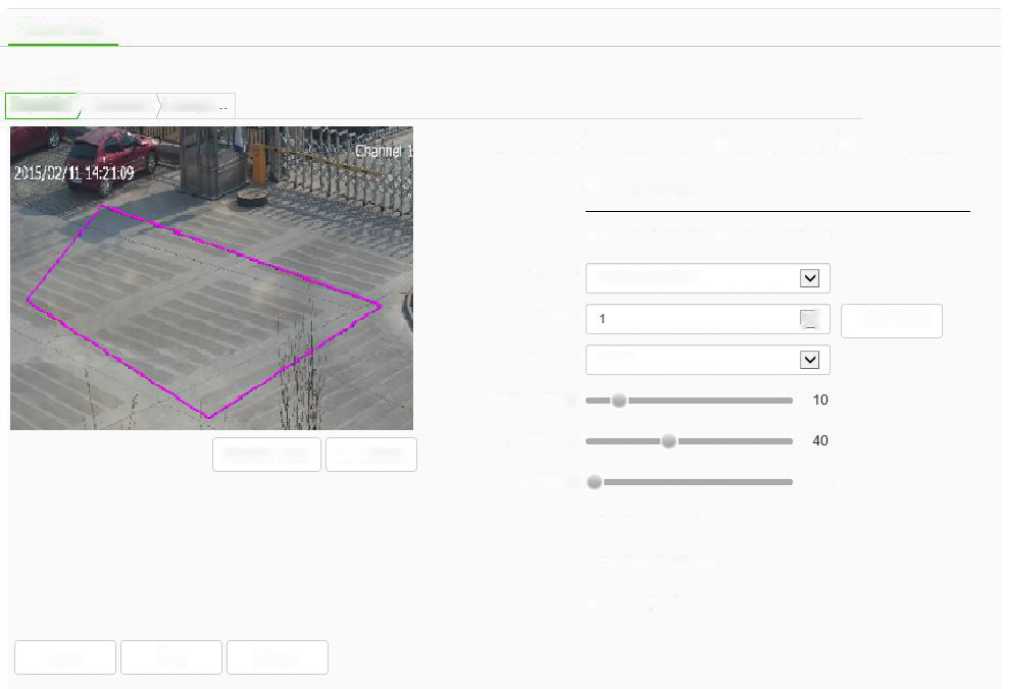
Create Rule
Event Selection
□ Demographics □ Crowd Detection
0 Enabled
Event Set \ Schedule Linkage.
0 Behavior Anal. ..
□ On Duty Dete…
□Video Detection nAudio Detection
Behavior Analysis
Event Type
_v] Rule Clear
Rule ID
Loiter
Specification Type
Event Time(s)
Sensitivity
Min Area
3 %
0 Show Event Count
0 Show Event Rule
□ Display Target
Save Next Cancel
Start to Draw Line Clear
Loiter setting interface
- Select the rule number, set the event as wandering, and check [Enable] to enable the rule.
- Draw a wandering detection area.
- Set the alarm time: indicate that an alarm will be triggered when the target is kept in the wandering state in the picture for the time specified.
- Set the minimum area to indicate that the target’s moving range (area percentage) in the detection area will trigger the alarm when the area is reached.
- Set the sensitivity. The larger the value is, the more sensitive it is.
- Click save after setting.
[Event Type] = > [Behavior Analysis] = > [Running]
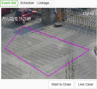
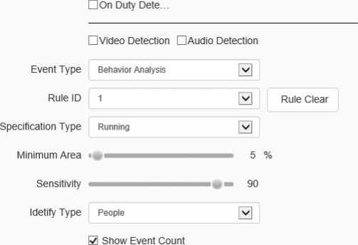
H Enabled
Event Selection 0Behavior Anal… □Demographics □ Crowd Detection
H Show Event Rule
□ Display Target
Save Next Cancel
Running setting interface
- Select the rule number, set the event as running, and check [Enable] to enable the rule.
- Draw a running detection area.
- Set the minimum moving distance per second, which means that the target’s moving speed (area percentage / second) in the screen is greater than the speed, and then it enters the running state.
- Click save after setting.
[Event Type] = > [Behavior Analysis] = > [Parking]
| | Event Set \ Schedule Linkag | e… |
| J •!’ Tb | |
| Start to Draw Line Clear | |
0 Enabled
- Draw the detection area of heat map.
- Set the minimum moving distance per second, which means that the target’s moving speed (area percentage / second) in the screen is greater than the speed, and then it enters the running state.
- Set whether to display alarm statistics, display alarm rules, two-way alarm and display target.
- Click save after setting.
[Event Type] = > [face detection]
- Draw the face detection area, click the “start drawing” button, draw the area, double-click to make the boundary automatically connect the head and tail.
- Set the maximum and minimum face size to represent the percentage of target width in the screen.
- Set the sensitivity. The larger the value is, the more sensitive it is. The detection rate will
improve, and the false detection will increase.
[Event Type] = > [Demographics]
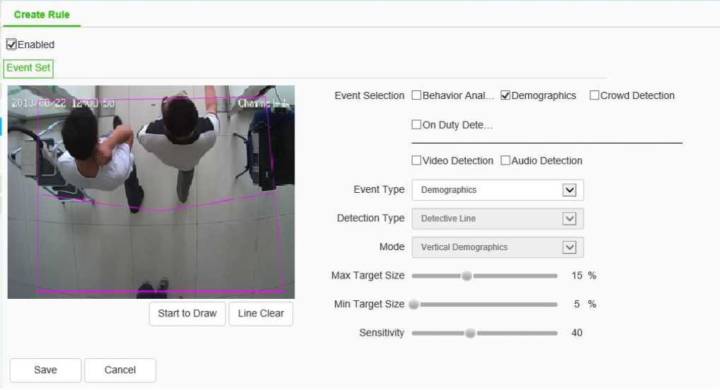
Demographics setting interface
- Draw the number detection area, click the “start drawing” button, draw the area, double-click to make the boundary automatically connect the head and tail.
- Draw a counting line, which indicates the decision line for the target to enter and leave the area.
- Set the maximum and minimum target size, which indicates the percentage of the target width in
the picture.
- Set the sensitivity. The larger the value is, the more sensitive it is. The detection rate will improve, and the false detection will increase.
Start to Draw
Line Clear
[Event Type] = > [Crowd Detection]
Create Rule
Event Selection
□ Behavior Anal… □Demographics 0 Crowd Detection
□ On Duty Dete…
Event Type
Event Time(s)
Sensitivity
SI Enabled
Event Set \ Schedule Linkage.
□Video Detection □Audio Detection
□ Show Event Count
□ Show Event Rule
Save Next Cancel
Crowd Detection
Crowd Detection setting interface
- Draw the crowd gathering detection area.
- Set the alarm time, which indicates that the alarm will be triggered after the alarm status continues to reach this time specified.
- Click save after setting.
[Event Type] = > [On Duty Detection]
- Draw the position detection area.
- Set the number of people on duty, and support single position and double position.
- Set the alarm time for leaving position, which indicates that an alarm will be triggered when the target is kept in the state of leaving position for the time specified.
- Set the sensitivity. The larger the value is, the more sensitive it is. The detection rate will improve, and the false detection will increase.
- Set the maximum and minimum target sizes, which indicates the size (percentage) of the target in the picture.
[Event Type] = > [Video Detection]
- Set whether to enable virtual focus diagnosis and scene transformation diagnosis.
- Set the sensitivity. The larger the value is, the more sensitive it is.
- Click save after setting.
- [event type] = > [Audio Detection]
- Set whether to enable signal loss detection and signal abnormality detection.
- Set the sensitivity. The larger the value is, the more sensitive it is.
- Click save after setting.
Note: after the detailed content is set, it is necessary to set the [Schedule] and [Linkage Mode] equipment to intelligently analyze and alarm linkage. Click [next] to enter [Schedule] setting. [Schedule]:
Set the effective time of the rule. By default, it is 24 hours a day. Click the blue bar to modify the deployment time, and then click save. Click [Next] to enter [Linkage Mode] setting.
[Linkage Mode]:
Set the alarm linkage function when the alarm occurs. For example: [Alarm Output], [Link Rec], [Linkage Snap], and etc.
Click [Save] to save the parameter settings. Click [Cancel] to restore the last saved parameter.
Advance Params
□ Enabled
Max Target Size
Min Target Size
Target Detection Se…
Target Confirmed Fr…
Save Cancel
Note: Advanced parameter setting, only under the guidance of the company’s technical personnel.
After all the above parameters are set, click Save to save the parameters; click [Cancel]to restore the last saved parameters.
Passenger flow statistics
Select channel number, report type and statistics time, and click export to export the corresponding report.
Heat chart statistics
Some models support heat chart statistics. Select channel number, report type and statistics time, and click “Statistics” button to perform heat chart statistics on space or time respectively, and display the imaging chart or line chart. Click “export” to export corresponding pictures or reports.
Face Statistics
Some models support face statistics. Select channel number, report type and statistics time, and click “Statistics” button to perform face statistics on age, gender and number of people respectively, and display statistics list, histogram, line chart or pie chart. Click “export” to export the corresponding XLS file.
[scenario Number]: you can select to view the alarm information of intelligent analysis event in a scenario.
[Event]: you can select to view the alarm information of one or all intelligent analysis events.
[Rule ID]: you can select to view the alarm status of some or all rules.
[Reset]: clear the number of events corresponding to the channel rule. When the event occurs again, start counting from 1.
[Clear]: Clear the alarm information displayed in the current list.
Face Detection – > Snapshot
Face Detection
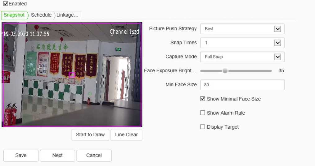
[Enable]: enable or disable the face detection function of the current channel.
[Snapshot]: you can set the [Picture Push Strategy], [Snap Times], [Capture Mode], [Face Exposure
Brightness] and [Min Face Size]
Description:
- [Picture Push Strategy] = >[Best]: it is necessary to screen out a small face map with the highestcomprehensive quality score in this trajectory.
- [Picture Push Strategy] = > [Fastest]: it is necessary to select a small face map that meets the comprehensive quality threshold in a short time to push.
- [Capture Mode] = > [Full Snap]: it means not controlled by the security boundary and not filtered by the security boundary threshold. All pictures are sent to the push module by default.
- [Capture Mode] = >[ High Quality]: it refers to filtering according to the default security boundary threshold value of the system, and sending the filtered results to the push graph module.
- [Capture Mode]= > [User Defined]: filter according to the security boundary value set by user-defined, and send the filtered result to the push graph module.
Face Detection – > Schedule
Face Detection
H Enabled

X Delete rd Delete All 0 2 4 6 8 10 12 14 16 18 20 22 24
Mon 0 2 4 6 8 10 12 14 16 18 20 22 24
Tue 0 2 4 6 8 10 12 14 16 18 20 22 24
Wed 0 2 4 6 8 10 12 14 16 18 20 22 24
Thu 0 2 4 8 8 10 12 14 16 18 20 22 24
0 2 4 6 8 10 12 14 16 18 20 22 24
Sat 0 2 4 6 8 10 12 14 16 18 20 22 24
Sun Save Next Cancel
The user can set the [deployment time] as required, and only detect the alarm within the set date and time period.
Face Detection – > Linkage Mode
Face Detection
S Enabled
Snapshot Schedule _ inkage
| Common Link | □ Alarm Output | □ Link Rec |
| □ Face RO I
□ Face Exposure 30 Miii v~| |
□ 1 | □ [1] Channel 1 |
Save Next Cancel
- Set [Linkage Mode]: to realize the alarm linkage after triggering the alarm, such as [Common Link], [Alarm Output], [Link Rec], etc.
- Click [save] to save the corresponding parameter settings. Click [Cancel] to restore the last saved parameter.
Schedule Recording – > Schedule Recording
Schedule Recording Packaging Mode
Recording Location ® SD/USB O FTP
Record Status stop [v]
□ Manual □ Schedule
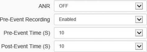
Mon
Tue
Wed
Thu
Fri
Sat
| 0 | 2 | 4 | 6 | 8 | 10 | 12 | 14 | 16 | 18 | 20 | 22 | 24 |
|---|---|---|---|---|---|---|---|---|---|---|---|---|
| 0 | 2 | 4 | 6 | 8 | 10 | 12 | 14 | 16 | 18 | 20 | 22 | 24 |
| 0 | 2 | 4 | 6 | 8 | 10 | 12 | 14 | 16 | 18 | 20 | 22 | 24 |
| 0 | 2 | 4 | 6 | 8 | 10 | 12 | 14 | 16 | 18 | 20 | 22 | 24 |
| 0 | 2 | 4 | 6 | 8 | 10 | 12 | 14 | 16 | 18 | 20 | 22 | 24 |
| 0 | 2 | 4 | 6 | 8 | 10 | 12 | 14 | 16 | 18 | 20 | 22 | 24 |
| 0 | 2 | 4 | 6 | 8 | 10 | 12 | 14 | 16 | 18 | 20 | 22 | 24 |
X Delete ® Delete All
Note:Offline recording will follow timing recording rule
Sun
Save Cancel
Schedule Recording setting interface
Switch the drop-down box to select the target video recording type, set the deployment time, retention time (days), and select the pre recording time and delay recording time.
[Record Status]: display the current equipment recording status.
[Record Start]: click the device to start recording after the test starts, and click the test stop to stop recording.
[Schedule]: four time periods can be set for timing recording, and the timing recording time period parameters can be set to the selected week.
[ANR]: when the network is disconnected, the video shall be recorded according to the time period of timed video recording.
Click [Save]to save the set[recording strategy] parameters, click [Copy To] copy the parameters of the current port number to other port numbers, and click [Cancel]to restore the last saved parameters.
Note: the equipment is required to support front-end storage for off network recording, and the timed recording fails after the off network recording is turned on.
Schedule Recording – > Packaging Mode
Schedule Recording Packaging Mode
Note: Storage policy is only for record on SDAJSB/NFS.
Free Storage Space
900 C (>=512M)
(MB)
Full Storage Scenario Overwrite
Save Cancel
Packaging policy setting interface
- Choose packing method: packing by time and packing by size. NVR will pack the video files according to the set time or size, and then start recording new video files.
- Select the processing mode of the system when the disk space is insufficient, such as “cycle delete”, “cycle delete (except for alarm file)” or “stop recording”.
- Click [Save] to save the corresponding parameter settings. Click [Cancel]to restore the last saved parameter.
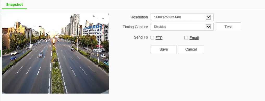
Snapshot setting interface
- After the[Timing Capture] is enabled, set the snapshot [interval] time.
- [Interval]: enter the time interval in the input box, and switch the drop-down box to select the interval unit.
- Check [FTP], take a picture and upload it to FTP server.
- Check [Email], take a picture and send it to the designated email.
[Test]: perform a snapshot operation to test the snapshot settings.
[Save]: save the above snapshot settings.
[Cancel]: restores the last set parameter.
Disk Management – > Disk Information
Disk Information
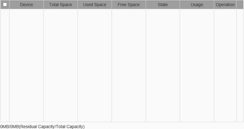
Initialize…
Disk information interface
The remaining capacity and total capacity of the current hard disk and virtual disk can be displayed in the interface, and the purpose of the disk can also be set. There are four options for the purpose of the disk: recording, backup, redundancy and read-only.
[Initialize Disk] select a disk in the disk list and click the “initialize disk” button. The system will pop up a prompt whether to initialize the disk. Click “OK” to initialize the disk.
Disk management – > Disk Policy
Some models support disk policy.
[Video Quota]: set the amount of disk space occupied by video files, in GB. If it is 0, it means that the device dynamically allocates space.
[Image Quota]: set the size of the disk space occupied by the snapshotd image file, unit: GB. If it is 0, it means that the device dynamically allocates space.
[Save]: save the settings.
[Cancel]: restores the last saved settings.
Disk management – > Storage Policy
Some models support storage policies.
Enter the conditions that trigger the [save policy], in the edit box of[ remaining disk space]. When the remaining disk space reaches the set value, there are three [save policies] :
- Stop recording: no more video packaging operation;
- Circular deletion: delete the earliest video file to create space for the latest video;
- Cycle delete (except alarm file): delete the earliest video file (except alarm video) to create space for the latest video. Click save after setting to take effect.
NFS – > FTP
FTP network storage
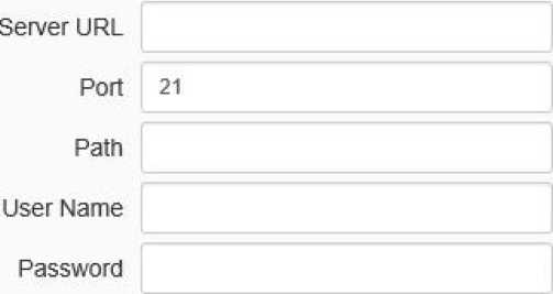
Save Test Gance!
FTP setting interface
After changing [Server URL], [Port], [Path], [User Name] And [Password], [Save] can set the
FTP server information. [Cancel] restore the last saved parameter.
[Test]: test whether the settings are correct and effective.
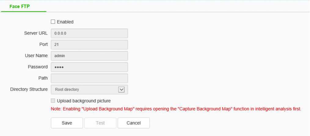
Face FTP setting interface
After changing [Server URL], [Port], [Path], [User Name], and [Password], [Path], [Directory Structure], [Save] can set FTP server information. [Cancel] restore the last saved parameter.
[Upload background picture]: when checked, two images, one large image and one small face image will be uploaded for each alarm; if not checked, only the small face image will be uploaded for each alarm.
[Test]: test whether the settings are correct and effective.
System – > Time
Time serial Port
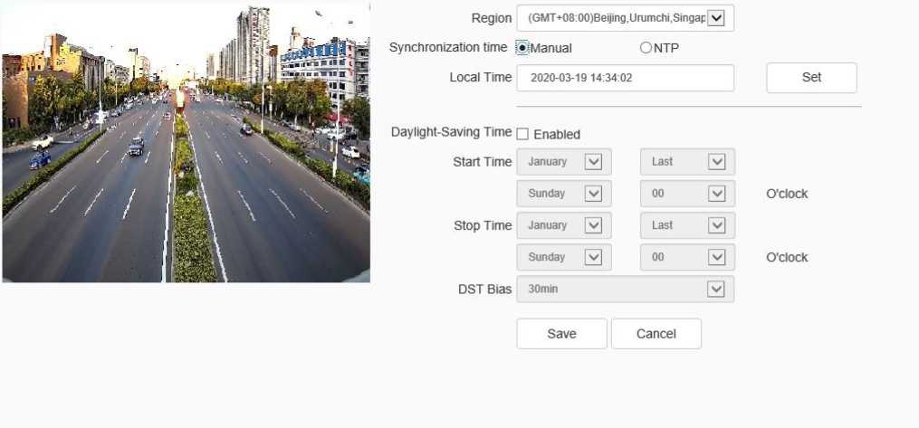
Time setting interface
Time zone: set the time zone information.
[Local Time]: real time display of local time.
[Synchronization Time]: the synchronization equipment time is the same as the local time.
[Daylight-Saving Time]: set whether daylight saving time is enabled. Set the time range and offset time for daylight saving time.
[NTP server]: enter the legal IP address of the server.
[Port]: enter the corresponding port number.
[Time Interval]: enter the interval of automatic time calibration.
[Test]: Test NTP automatic timing.
Click [save] to save the currently set parameters. Click[Cancel] to restore the last saved parameter.
System – > Serial Port
Time Serial Port
Serial Port Set
| Port Name | COM2 | V | |
| Baud Rate | 9600 | V | |
| Parity Bit | None | V | |
| Byte Size | 8 | V | |
| Stop Bit | 1 | V | |
| Work Mode | Transparent Channel | V | |
| Protocol Set | |||
| Port Name | COM2 | V | |
| Protocol | □OME_PELCO_P | V | |
| Address | i | •-
r |
Save
Cancel
Serial port setting interface
Some models support serial port settings. It is divided into [serial port setting] and [protocol setting].
[Serial Port Set] requires the user to select [serial port number], [baud rate], [check bit], [data bit], [stop bit] and [working mode].
For [Protocol Set], you need to select [channel number], [serial port number], [protocol] and [address].
Note:
- Because the functions of different models are different, please refer to the actual interface.
- Some models support the baud rate option.
Users – > Users
Users Connection
| No. | User Name | Authority | Edit | Delete | |
| 1 | Admin | Admin | Edit | ||
Add
User management setting interface
[New]
To add a new user, you need to enter the user name, password and permission. The user name and password can only be entered in English letters and numbers. After the above three items are filled in, click the [save] button.
Note: only users with administrator rights can add and modify users.
[Edit]
In the user list, click [edit] to open the password modification prompt box, input the old password, new password and confirm the password, and then click Modify.
[Remove]
In the user list, click [delete] to open the prompt box and click OK.
User management – > Connection
Users Connection
Connection yj Refresh
| Channel No. | Network Mode | Client IP | User Name | ■ |
| Channel No.1 1st Stream | TCP | 192 168.15.60 | Admin | |
| Channel No.1 1st Stream | TCP | 192 168.15.60 | Admin | |
Connection information interface
Display the detailed list of connecting / logging in the device, including channel type, network mode, client IP and user name. Click [Refresh] to update the list.
Maintenance – > Maintenance
Maintenance Upgrade
a”i. I
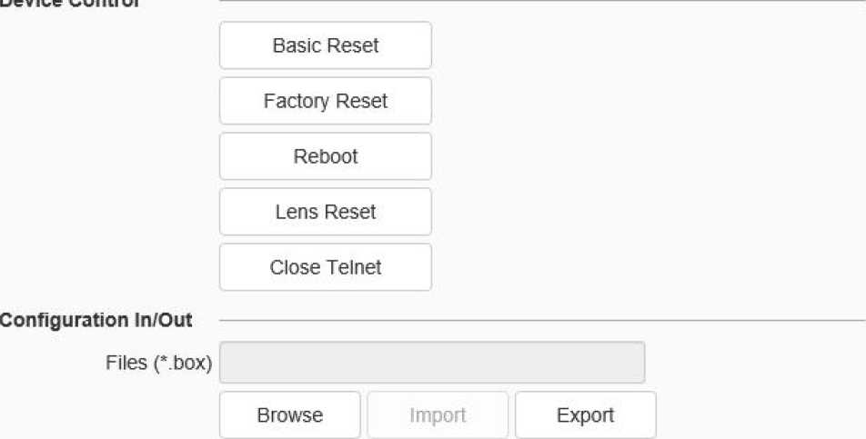
Note: User need to manuafly input new iP to login again when IP address changed.
System maintenance interface
[Device Control]: allows customers to perform [restore default], [simple restore], [restore factory], [restart equipment], [aperture correction], [lens reset], [disable / enable ABF], [Open Telnet] and other operations. Because the functions of different models are different, please refer to the actual interface.
[Import ]/ [Export]: used for equipment maintenance, mainly divided into three categories:
- [Event Server] options include alarm time period and linkage item setting information, excluding intelligent analysis.
- [Smart Analytics ]options include settings related to intelligent analysis, including rules, time periods, etc.
- [System Setting] options include all setting information except the above alarm, intelligent analysis, logo, storage strategy and local setting, including video parameters, HD parameters, character superposition, video recording strategy, network setting and other information.
Maintenance – > Upgrade
Maintenance Upgrade
Version Information
Factory ID ID0000801940340211020431
MAC 00:50::c2:22:15:66
Hardware Version 103e
Kernel Version NVSS_V20.5.1.20200319
Web Version 6.1.20.318
cgi Version CG!_V3.0.0.20200318
onvit Version ON VIF_V3.3.0.20200318
p2p Version P2P_V3.3.0.20200318
rtmp Version RTMP_V3.3.0.20200318
rtsp Version RT8P_V3.3.0.20200318
app Version APP_V3.3.0.20200318
Firmware Upgrade
Upgrade File
C-box,* bin)
Browse
Upgrade
System upgrade interface
[Version Information]: it includes equipment information such as [factory ID], [MAC], [Hardware Version],[ Kernel Version] and [Web Version].
[Firmware Upgrade]: the user can select a local legal. Box or. Bin file to upgrade the device remotely. The upgrade operation of the kernel program shall be conducted under the guidance of the company’s technical personnel.
[Browse]: find the upgrade file in the pop-up window.
[Upgrade]: upgrade to the latest version through the network.
[Record Videos/Live Snapshots/Playback Snapshots/Video Clips/Downloaded Files/VCA Snapshots/Protocol Type]: the storage path can be set.
[Local Capture Format]: select [JPG], [BMP]. To send the snapshotd pictures to FTP and email, JPG must be selected.
Start to Draw Line Clear
Scene
Scene Cruise Time
Type
Schedule
□ Enabled
□_ JEI 00:00 * ~ 23:59 * 0
©Perimeter(EW) OTripwire(EW)
(•) Pre-arranged P OCustomized
© Snapshot and link with white light
O Snapshot and link with white light and single alert sound
O Snapshot and link with bursting multi-stage sound and light
O Snapshot and link with gradient multi-stage sound and light
Save Cancel
Alert setting interface
In the alert setting interface, the user can set alert parameters according to the actual situation or preference of the site.
Plan setting:
Step 1 check enable effective alert algorithm.
Step 2 select [Type], set perimeter alert or trip line alert, and set the effective time of alert scene.
Step 3 adjust the scene and draw warning area or warning line. Perimeter alert default full screen is alert area. If you need to adjust, you need to clear the line and draw again.
Step 4 select a preset alert plan.
Step 5 click the “save” button to complete the algorithm setting and exit the alert setting interface to take effect.
User-defined settings:
Step 1 check enable effective alert algorithm.
Step 2 select alert type: perimeter alert or trip line alert, and set the effective time of alert scene.
Step 3 adjust the scene and draw warning area or warning line.
Step 4 select custom alert template.
Step 5 set linkage item or advanced parameter. Among them, linkage items can be set with three levels of warning at most, and each level of warning effect can be set separately.
Step 6 click the “save” button to complete the algorithm setting and exit the alert setting interface to take effect.
Description:
- The device supports setting up multiple scenes. You can set up different scenes through the above steps.
- In the perimeter alert, the plan of “explosive multi-level acoustooptic alert” is: after the target intrudes into the alert area, the white light flashes strongly and the voice calls.
- “Progressive multi-level acoustooptic alert” plan is: it is divided into three levels by default, and the warning effect is enhanced step by step. When the retention time in the upper level is greater than the set value, it will enter the next level.
- The linkage settings in the user-defined template can set up to three levels of linkage, and the linkage items can be set separately in each level of settings.
- In linkage setting, the constant light option of linkage white light indicates that the white light will be turned on in case of alarm, and will be turned off automatically after the alarm is cancelled.
- Advanced parameters in the user-defined template include: Defense week, detection mode, trigger alarm target, trigger sensitivity, maximum tracking time, display rule and target box setting, etc.
- The alert types are divided into perimeter alert and trip line alert, aiming at the intrusion area, departure area and cross-border behavior. The perimeter alert is the intrusion zone alert by default. Users can modify the detection mode in the advanced settings of the user-defined template.
- The warning detection target defaults to person and vehicle. Users can user-defined advanced settings according to specific needs.
- The longest tracking time takes effect when the linkage tracking, which means that when the time is reached, the tracking action will stop and return to the alert monitoring scene.
- The user-defined alert tone can be set in the following two ways: 1. Download audiomaker.exe software, record the warning tone according to the help document of the software, make an upgrade package, and then download it to the camera through the camera’s web page upgrade mode. 2. Download the mobile client through the QR code button in the preview interface, and record and upload the warning tone for the devices connected to the Internet that support custom warning tone.
- Simple Troubleshooting
Possible causes:
- Plug and unplug the U disk or micro SD card, and operate in case of power failure;
- There is a problem with the partition information of the disk, which causes the device to be unrecognized and needs to be reformatted;
- The card is loose, unplug it again after power failure, and then start the equipment;
-
- unrecognized wireless network card
-
Possible causes:
- Plug and unplug the wireless network card, which needs to be operated in case of power failure;
- The static electricity causes the network card to enter the protection state, so the equipment needs to be powered on again;
- The working state of the wireless network card is unstable, and the hardware of the wireless network card is faulty, which needs to be replaced; it is necessary to obtain the latest list of wireless network cards supported from the company.
Troubleshooting steps:
- Confirm whether the camera is powered on normally, whether the host network card and driver are normal, whether the network cable connection is normal, and whether the network topology connection is smooth;
- Connect the host computer and HD network camera directly with the cross network cable. If it still fails, reset and retest the camera;
- Restart the searcher software, or select the IP in the same network segment with the device;
- Restart the computer;
- If there are spare hosts and HD network cameras, they can be replaced for testing;
- Check whether the equipment has passed the 4G card networking;
- If you still have any questions, please contact us;
-
- image cannot be connected normally in IE
-
- Download and install IE control for the first login;
- Add the device IP to the trusted address;
- Re install IE control;
-
- after logging in the network front-end product, it is found that the video is not the video
-
of the front-end product
Possible causes: there are network devices with the same IP and MAC addresses in the network;
Troubleshooting steps:
- Disconnect the network connection of the current device, Ping the corresponding IP, and check whether there is a return packet;
- Use a searcher to search for devices with duplicate IP addresses, disconnect the device network, and then search for verification;
- For public network connection, the port selected during login is the port mapped to other devices;
-
- the camera can be pinged but cannot log in normally
-
Possible causes:
- Port 3001 is blocked by firewall;
- The port number used for login is incorrect;
- Incorrect user name and password for login;
- Too many clients connected, the number of device connections is full;
- The camera has set up a black and white list, and is forbidden to log in from the current computer. You need to modify the settings first;
- Check whether the listening port of the device is the same as the port connected and used on the software through the searcher;
-
- UDP cannot connect to video
-
Possible causes:
- Other clients on the same machine have connected to the video;
- The port of UDP conflicts with that of other application programs of the computer. Modify the device IP to test;
-
- the videos of two network front-end products are alternately connected or disconnected Possible causes:
-
- IP address conflict can be viewed by Searcher;
- MAC address conflict can be checked by Searcher;
- The IP address conflicts with the IP address of other computers;
Troubleshooting steps:
- Confirm that the host IP address and the network camera address are set in the same network segment, if not in the same network segment, change to the same network segment;
Note: for example, in different network segments, the routing of these two network segments must be ensured.
- Confirm the version of IE, it is recommended to install IE 6 and above;
- Confirm the normal installation of the video card driver and DirectX, it is recommended to install the latest video card driver and DirectX;
- Temporarily shut down the anti-virus software and software firewall for further testing; temporarily shut down the system’s own firewall for further testing;
- Delete the previously downloaded control when connecting, reconnect and download the installation control test;
- Replace the main engine for test;
- If you still have any questions, please contact us;
-
- unable to connect sub code stream
-
Possible causes: there are too many other clients connected, and the number of connections is full;
Troubleshooting steps: please confirm that the correct protocol, address and baud rate have been selected in the software;
Possible causes:
- Please confirm that the address setting in the software is correct;
- If easy7 software is used, ensure that “system settings -[ host] interface – Video Channel – Equipment [address and protocol] content settings are correct”;
- If there are still problems, please contact our after-sales technical personnel;
Troubleshooting steps:
- Exit the software, check the CPU utilization of the machine, and eliminate the cause of insufficient configuration of the machine itself or whether the host is poisoned;
- Ping the device to see if there is packet loss;
- Use the bandwidth test software to test the network bandwidth. If the bandwidth is insufficient or unstable, please contact the network operator;
- When the network bandwidth is insufficient and the video fluency is guaranteed, we first consider reducing the resolution of the image; in the case of not changing the resolution, in the IE image quality setting, change to the variable bit rate mode, and increase the values of the best quality and the worst quality in the image quality, so as to appropriately reduce the video quality;
- Whether the system performance is insufficient due to too many functions being turned on, such as character stacking, key area, intelligent analysis and other functions occupying the performance, first turn off some functions and then verify whether the video is normal
again;
-
-
- If the video connection display is normal, but the image is black screen or seriously distorted
-
Other features: no character superimposition, or the image is seriously distorted but can display normally after zooming in
Possible causes:
- DirectX version is lower than 9.0c;
- The video card driver is incorrect, resulting in the DirectX acceleration function not starting, windows The performance of Server 2003 is more obvious;
- Full screen occlusion is set;
-
- If the video can be connected under IE, but the display in the software is abnormal Troubleshooting steps:
-
- Confirm whether the software version is correct;
- Confirm the correctness of “IP address” and “server type” of “server edit information” in the software; it is recommended to adopt “main code stream + TCP” mode in LAN, and WAN can adopt “bystream + TCP” mode;
- Confirm that the video is connected to the main interface of the software;
- Restart the software and connect;
- Confirm that the driver and wiring of the corresponding sound card of the host are correct, and you can play music to test whether it works;
- Confirm that “audio and video stream” is selected instead of “video stream”;
- Verify the correctness of front-end pickup equipment and wiring;
- Refer to 6.6.2 audio signal weak solution;
-
- weak audio signal
-
Troubleshooting steps:
- Check whether the audio input type is selected correctly. The default audio input of the external passive mic model is MicIn. If the external active audio is used, it needs to be set to LineIn;
- Adjust the audio input volume value through IE, and check whether it is too low;
- The back-end sound playing unit must be an active speaker;
Troubleshooting steps:
- Confirm that the input and output signal wiring mode of the alarm is correct, ensure that the signal is the switch signal, and do not connect the wiring wrongly or falsely;
- Check whether the port setting of the network video server is correct and whether the enabling setting of the input and output ports is correct through IE;
- Confirm whether the alarm input and output equipment is normal;
Possible cause: parameters can be saved normally only after 1 minute of setting, unless automatic restart or IE click [system restart], abnormal power failure, etc. may cause parameters not to be saved normally.
-
-
- failure to restart the system as required
-
Possible cause: some parameters have been changed. You need to restart the system, otherwise it may not take effect.
Possible cause: when the camera formats the U disk and micro SD card, special partition operations are carried out, resulting in part of the capacity cannot be recognized on the computer. If you want to continue to use ordinary storage media, you need to reformat it on your computer.
Solution:
- Download the installation software BOOTICE.EXE;
- Insert the USB stick or micro SD card to be formatted into the computer. Open the software, select the corresponding U disk in the target disk, and then select partition management – > repartition and format – > select USB-FDD mode – > select FAT32 or NTFS system format – > input volume label, such as “U disk” – > finally click OK to finish the U disk repartition.
- After-sales Services
For the high-definition network series camera produced in our company, we promise one-year warranty. During the product warranty period, the company provides free maintenance services, but in case of the following circumstances, the material cost and labor cost shall be charged as appropriate:
- The camera is damaged due to the operation not in accordance with the user manual;
- Lightning, fire and irresistible natural disasters;
- Damage caused by matching problems due to poor product design of other manufacturers;
- Due to our continuous adoption of new technology, product parameters are subject to change without notice.
- Lightning Protection and Surge Protection
Lightning and surge protection shall be considered for outdoor cameras. On the premise of ensuring electrical safety, the following lightning protection measures can be taken:
- The signal transmission line must be kept at least 50 meters away from the high-voltage equipment or high-voltage cable;
- Outdoor wiring shall be routed under the eaves as much as possible;
- For the open area, the sealed steel pipe must be buried for wiring, and the steel pipe shall be grounded at one point, and the overhead wiring is absolutely prohibited;
- In strong thunderstorm area or high induced voltage area (such as high-voltage substation), additional high-power lightning protection equipment and lightning rod must be installed;
- The lightning protection and grounding design of outdoor devices and lines must be considered in combination with the lightning protection requirements of buildings, and meet the requirements of relevant national standards and industry standards;
- The system must be equipotential grounded. The grounding device must meet the double requirements of system anti-interference and electrical safety, and shall not be short circuited or mixed connected with the zero line of the strong current network. When the system is grounded separately, the grounding impedance shall not be greater than 4 Q, and the cross-sectional area of the grounding conductor shall not be less than 25mm2.
Lightning rod
Video lightning arrester
Power lightning arrester
The camera must be installed within the range of 45°under lightning rod.
Communication lightning arrester
The resistance of grounding conductor is not greater than 40
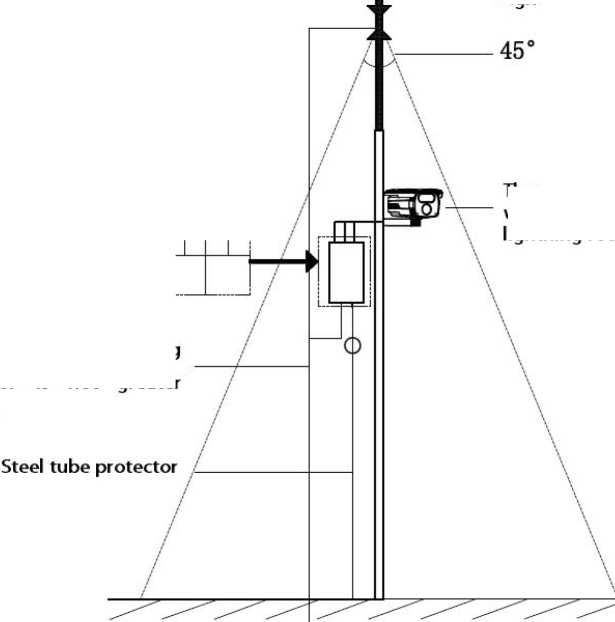
- default parameters and recommended configuration
Default parameters of HD series webcam
[default IP parameters] IP address: 192.168.1.2; subnet mask: 255.255.255.0;
Gateway: 192.168.1.1; DNS: 192.168.1.1
User name: admin Password: admin
[onvif protocol connection] VLC connection address: rtsp://192.168.1.2:554
User name: admin Password: admin
Recommended system configuration
| Type | Recommended computer configuration |
| CPU | Intel Core i7 2600 quad core and above |
| Memory bar | 4G and above |
| Hard disk space | >250G |
| operating system | Windows 7 and above |
| Browser | IE 8 and later |
| Direct X | 10.X |
| Resolution | 1920 x 1080 or higher |
| Network card | 10 / 100 / 1000 Base-T Ethernet |
| Graphics card | Independent video card / video memory 512M |